COPYRIGHT © 1999 CANON INC. CANON imageRUNNER 400/330 REV.0 JAN. 1999 PRINTED IN JAPAN (IMPRIME AU JAPON)
2-13
CHAPTER 2 BASIC OPERATION PROVIDES
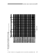
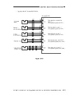
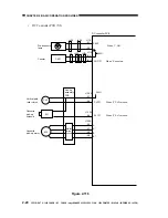
Inputs to the DC Controller PCB (2/4)
Figure 2-109
PS11
PS12
PS13
DC controller PCB
PS14
J418
J438
J424A
J471
J472
J470
Vertical path
sensor
Right door
open/closed sensor
Left door
open/closed ensure
Waste toner ensure
PS11S
PS12S
5V
5V
5V
PS13S
5V
PS14S
When paper has moved past the
sensor, ’1’.
(The light-blocking plate is at PS11.)
When the right door is open, ’1’.
(The light-blocking plate is at PS12.)
When the left door is open, ’1’.
(The light-blocking plate is at PS13.)
When the waste toner case is full, ’0’.
(The light-blocking plate is not at PS14.)
J108
-B9
-B8
-B7
J108
-B15
-B14
-B13
J114
-6
-5
-4
J102
-A12
-A11
-A10
PS40
Fixing assembly
inlet paper sensor
5V
PS40S*
When paper is at the sensor, ’0’.
(The light-blocking plate is not at PS40.)
J114
-A3
-A2
-A1


