COPYRIGHT © 1999 CANON INC. CANON imageRUNNER 400/330 REV.0 JAN. 1999 PRINTED IN JAPAN (IMPRIME AU JAPON)
10-21
CHAPTER 10 EXTERNALS/AUXILIARY MECHANISMS
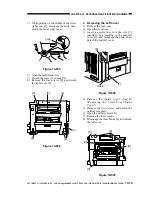
6) Open the delivery assembly.
7) Slide out the upper cassette.
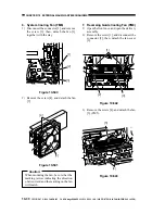
8) Remove the five screws, and detach the
inside cover.
Figure 10-512
C. Control Panel
1. Removing the Control Panel
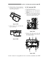
1) Remove the inside cover.
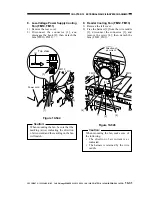
2) Remove the screw, and detach the magnet
plate [1] from the top of the control panel.
Figure 10-513
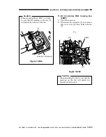
3) Free the shorting connector harness [2]
shown in the figure from the edge saddle
[3].
Figure 10-514
[9]
[9]
[1]
[2]
[3]

