COPYRIGHT © 1999 CANON INC. CANON imageRUNNER 400/330 REV.0 JAN. 1999 PRINTED IN JAPAN (IMPRIME AU JAPON)
10-25
CHAPTER 10 EXTERNALS/AUXILIARY MECHANISMS
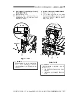
G. Accessories Power Supply
PCB
1. Removing the Options PCB
1) Remove the rear cover.
2) Remove the flywheel.
3) Remove the scanner control fan unit
(FM17, FM18).
4) Remove the screw [2], and disconnect all
connectors; then, detach the accessories
power supply PCB [1].
Figure 10-526
Figure 10-527
[2]
[1]
[1]
[2]
[3]
[4]
[1]
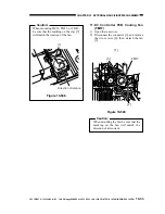
2. Mounting the Options PCB
1) Remove the screw from the rear of the
copier's right cover,and displace the rear
of the right cover toward the outside.
2) Fit the hooks on the PCB in the cut-offs
shown in the figure to mount.
Hooks.
Cut-offs
Displace toward the outside.
Power supply unit
Figure 10-526-1
H. Fans
Caution:
If the screws used to mount the fan are
not tightened fully, abnormal noise may
be heard when the fan is rotating. Be
sure to tighten the screws fully when
mounting the fan.
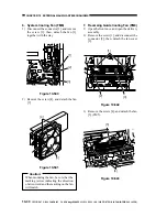
1. Feeder Fan (FM1)
1) Remove the screw, and detach the transfer
charging roller unit from the feeding
assembly.
2) Remove the feeding assembly.
3) Remove the three bushings [1], and
disengage each hook of the gear [2]; then,
detach it.
4) Remove the screw, and detach the static
eliminator [3].
5) Move the feeder fan assembly [4] in the
direction of the arrow in the figure to
detach it from the mount.

