CHAPTER 10 EXTERNALS/AUXILIARY MECHANISMS
10-26
COPYRIGHT © 1999 CANON INC. CANON imageRUNNER 400/330 REV.0 JAN. 1999 PRINTED IN JAPAN (IMPRIME AU JAPON)
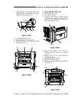
6) Disconnect the connector [5], and detach
the feeding belt [6] as if to displace it.
Figure 10-528
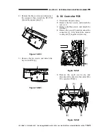
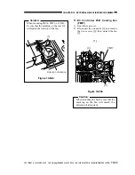
7) Disengage the hook [8] of the feeder fan
cover [7] with a small flat-blade
screwdriver, and detach the cover.
8) Remove the feeder fan [9].
Figure 10-529
2. Fixing Assembly Heat Discharge
Fan 1/2 (FM2/3)
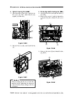
1) Open the front door.
2) Open the delivery assembly.
3) Remove the screw 1, and disconnect the
heat discharge connector cover 2.
4) Disengage the hooks [3] [4], and detach
the fan cover.
[5]
[6]
[7]
[8]
[9]
[4]
[4]
[3]
[3]
[5]
[5]
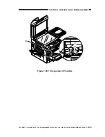
Figure 10-530
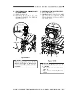
[1]
[2]
Figure 10-529-1

