CHAPTER 14 TROUBLESHOOTING
14-22
COPYRIGHT © 1999 CANON INC. CANON imageRUNNER 400/330 REV.0 JAN. 1999 PRINTED IN JAPAN (IMPRIME AU JAPON)
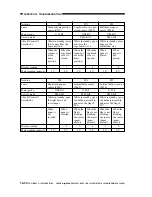
F. Electrical System
1
Replacing the Major Part
Parts
Image processor
PCB
Composite power
supply PCB
Laser scanner
unit
Laser unit
CCD unit
Scanning lamp
DC controller
PCB
Standard white
plate
Control panel LCD
Multifeeder size
detecting volume
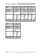
Fixing assembly
Fixing cleaning
belt
n
Before Replacement
Generate stored data of ADJUST,
OPTION, and COUNTER.
n
After Replacement
1) Execute RAM clear (image
processor PCB).
2) Enter data under AJDUST and
OPTION.
3) Execute shading auto correction 2.
4) Execute density correction.
4-1) Execute standard white plate
density read.
4-2) Execute density auto correction.
4-3) Execute DZ density auto
correction.
n
After Replacement
1) Enter the values indicated on the
label attached to the composite
power supply PCB in service mode.
2) Execute shading auto correction 1.
3) Execute auto density correction.
1) Execute shading auto correction 1.
2) Execute auto density correction.
1) Execute shading auto correction 2.
2) Execute auto density correction.
Adjust the coordinate position of the
analog touch panel.
Store the paper width basic value for
the multifeeder.
Nip (as indicated?)
Execute cleaning belt clear.
FUNCTION>MISC-P>
P-PRINT
FUNCTION>CLEAR>
IP
YAKUNUKE
FUNCTION>CCD>
MAN-ADJ
FUNCTION>DENS>
WHITE-ME
FUNCTION>DENS>
PD-DENS
FUNCTION>DENS>
DZ-DENS
FUNCTION>DENS>
DZ-ME
FUNCTION>CCD>
CCD-ADJ
Same as [A] above.
FUNCTION>CCD>
CCD>ADJ
Same as [A] above.
FUNCTION>CCD>
MAN-ADJ
Same as {A] above.
FUNCTION>PANEL>
TOUCHKEY
FUNCTION>CST>
MF-A4R, A6R, A4
FUNCTION>FIXING>
NIP-CHK
COUNTER>MISC>
FIX-WEB
[A]
Description/Service mode


