CHAPTER 12 INSTALLATION
12-48
COPYRIGHT © 1999 CANON INC. CANON imageRUNNER 400/330 REV.0 JAN. 1999 PRINTED IN JAPAN (IMPRIME AU JAPON)
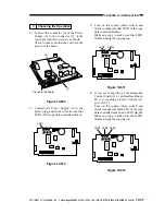
17) Connect the telephone line to the controller.
If the connection is only to the controller,
connect the modular jack cable to its
connector LINE [24].
If the extension function of the controller
is to be used, connect the existing
telephone or a fax to its connector TEL
[25], and connect the telephone line to its
connector LINE [24].
Figure 12-615
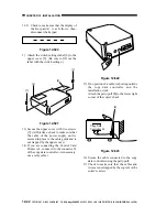
18) Place a call to the service station to ask for
initial settings for the controller. (LED4
[26] (red) will flash.)
Figure 12-616
19) Place a call to the service station to find
out whether the initial settings for the
controller ended. If the attempt ended in
failure, go back to RAM initialization,
i.e., perform from step 12) to 14) and try
initial settings once again.
Caution:
Be sure to check with the service station
to make sure that the settings of the
controller are correct.
20) Try to place a call to the service station.
Press the push switch (SW4) [21] on the
board of the controller.
LED6 [27] (red) should turn on: when a
transmission ends successfully, the LED
should turn off; if it ends in failure, the
LED (red) should flash.
Press the push switch SW4 [21] once
again if the LED6 [27] flashes.
A press on the push switch SW1 [28]
while LED6 [27] is flashing will stop the
ongoing transmission attempt.
Figure 12-617
LED1 LED2 LED3
2
1
LED5
LED6
LED4
IC6
SW1
SW4
SW3
6
1
BAT1
CN4
1
2
CN3
CN2
[25] [24]
SW2
LED1 LED2 LED3
2
1
LED5
LED6
LED4
IC6
SW1
SW4
SW3
6
1
BAT1
CN4
1
2
CN3
CN2
[26]
SW2
LED1 LED2 LED3
2
1
LED5
LED6
LED4
IC6
SW1
SW4
SW3
6
1
BAT1
CN4
1
2
CN3
CN2
[27]
SW2
[28]
[21]


