COPYRIGHT © 1999 CANON INC. CANON imageRUNNER 400/330 REV.0 JAN. 1999 PRINTED IN JAPAN (IMPRIME AU JAPON)
7-61
CHAPTER 7 PICK-UP/FEEDING SYSTEM
E. Registration Roller Assembly
1. Removing the Registration Roller
1) Remove the following parts:
Drum unit
Fixing assembly knob
Inside cover
Developing assembly
Transfer charging roller unit
Rear cover
Flywheel
Scanner motor cooling fan mount
(FAM17, FM18)
Low-voltage power supply cooing
fan unit
Rear harness unit (2 screws)
Power cord mount
Low-voltage cord mount
Accessories power supply PCB
Scanning lamp
Registration clutch
Main drive unit
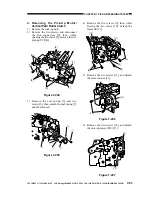
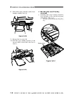
2) Remove the transfer guide positioning
boss [1], spring [2], and two E-rings [3]
from the rear of the copier.
Figure 7-232
[1]
[2]
[3]
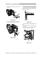
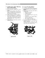
b. Mounting the Upper Feeding Guide
Check to make sure that the feeding
assembly inlet bushing 1 is fitted correctly in
the shaft hole of the upper feeding guide 2 and
it has the spatial relationship shown in the
figure.
[2]
[2]
[1]
[1]
[A]
[A]
Figure 7-231-2

