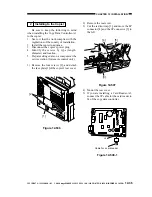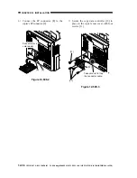
COPYRIGHT © 1999 CANON INC. CANON imageRUNNER 400/330 REV.0 JAN. 1999 PRINTED IN JAPAN (IMPRIME AU JAPON)
12-31
CHAPTER 12 INSTALLATION
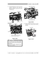
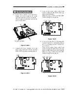
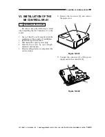
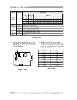
3) Connect the harness of the control card
with the connector from which the
shorting connector was removed in the
foregoing step.
Figure 12-407
Caution:
Check to make sure that the grounding
wire of the control card and the harness
will not come into contact with the drive
assemblies.
If they are in contact, arrange them once
again by re-routing.
Figure 12-408
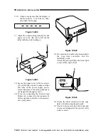
4) Place the plastic film sheet over the
opening in the control panel (display
opening).
Figure 12-409
Screws
Connectors
Control panel
Screw (that comes
with the unit)
Screw
Connector
Connector (from which the shorting
connector has been removed)
Grounding wire
Lever of the solenoid
Interlocking assembly
Plastic film


