COPYRIGHT © 1999 CANON INC. CANON imageRUNNER 400/330 REV.0 JAN. 1999 PRINTED IN JAPAN (IMPRIME AU JAPON)
10-23
CHAPTER 10 EXTERNALS/AUXILIARY MECHANISMS
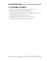
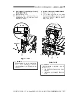
4) Remove the three screws, and disconnect
the connector; then, detach the DC PCB
[4] and the support plate [5].
Figure 10-519
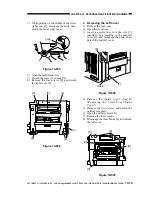
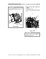
5) Remove the ten screws, and detach the
key switch PCB [6].
Figure 10-520
D. DC Controller PCB
1) Disconnect the power plug.
2) Remove the four screws, and detach the
rear cover.
3) Remove the three screws, and detach the
flywheel.
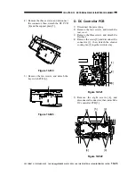
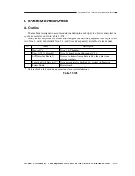
4) Remove the screw [2], and disconnect the
connector [3]; then, detach the cleaner
cooling fan [1] together with its stay.
Figure 10-521
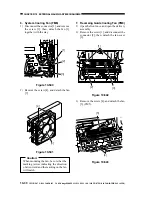
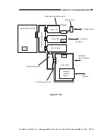
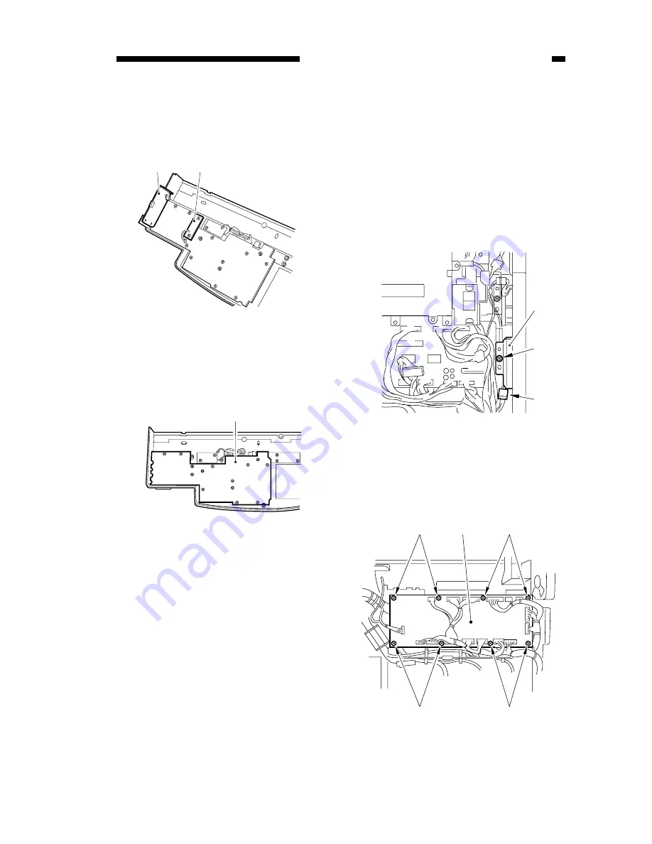
5) Remove the eight screws [4], and
disconnect all connectors; then, detach the
DC controller PCB [5].
Figure 10-522
[4]
[5]
[6]
[1]
[2]
[3]
[4]
[4]
[4]
[4]
[5]


