COPYRIGHT © 1999 CANON INC. CANON imageRUNNER 400/330 REV.0 JAN. 1999 PRINTED IN JAPAN (IMPRIME AU JAPON)
5-11
CHAPTER 5 LASER EXPOSURE SYSTEM
A. Laser Scanner Assembly
1. Removing the Laser Scanner Unit/
Laser Unit
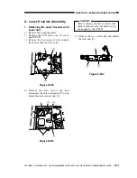
1) Remove the copyboard glass.
2) Remove the CCD unit cover, IP cover,
and IP PCB.
3) Remove the five screws [2], and detach
the laser scanner unit cover [1].
Figure 5-500
4) Remove the four screws [4], and
disconnect the three connectors [5]; and
detach the laser scanner unit [3].
Figure 5-501
Caution:
After mounting the laser scanner unit,
check to make sure that the harness [6] is
not trapped by the IP PCB.
5) Remove the two screws [8], and detach
the laser unit [7].
Figure 5-502
[2]
[1]
[2]
[2]
[6]
[5]
[4]
[5]
[4]
[4]
[3]
[8]
[8]
[7]

