COPYRIGHT © 1999 CANON INC. CANON imageRUNNER 400/330 REV.0 JAN. 1999 PRINTED IN JAPAN (IMPRIME AU JAPON)
9-21
CHAPTER 9 FIXING SYSTEM
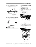
3. Be sure to mount the insulating bush by
orienting it as shown in the figure.
Figure 9-222-2
4. Be sure to orient the fixing roller so that
the longer bushing is toward the rear.
Figure 9-222-3
Caution:
Do not leave out the C-ring.
4. Removing the Lower Separation
Claw
1) Open the front door.
2) Open the delivery assembly.
3) Take out the fixing assembly.
4) Remove the following from the fixing
assembly, and detach the separation claw
unit [5]:
Positioning pin [1] (1 pc.)
Screw [2] (1 pc.)
Spring [3] (2 pc.)
Grounding screw [4] (1 pc.)
Figure 9-223
5) Remove the screw [6] (1 each), and detach
the two lower separation claw units [7];
then, detach the two lower separation
claws [9] while paying attention to the
springs [8] (2 each).
Figure 9-224
Insulating bush
Rear metal plate
Front metal plate
(rear)
(front)
c-ring
[3]
[4]
[3]
[1]
[2]
[9]
[6]
[6]
[8]
[7]

