COPYRIGHT © 1999 CANON INC. CANON imageRUNNER 400/330 REV.0 JAN. 1999 PRINTED IN JAPAN (IMPRIME AU JAPON)
12-47
CHAPTER 12 INSTALLATION
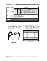
Figure 12-612
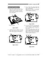
15) If LED5 [22] (red) has turned on, set the
bits of the DIP switch (SW2) [20] on the
board of the controller as shown, and
press the push switch (SW4) [21].
A press on the push switch (SW4) [21]
will turn off LED5 [22] (red), indicating
that the RAM has been initialized.
SW2 bits
SW2-1
SW2-2
SW2-3
SW2-4
SW2-5
SW2-6
SW2-7
SW2-8
Settings
OFF
OFF
OFF
ON
OFF
ON
See step 9).
OFF
Table 12-603
Figure 12-613
16) Shift the bit of the DIP switch (SW2-6)
[23] on the board of the controller to OFF.
Figure 12-614
LED1 LED2 LED3
2
1
LED5
LED6
LED4
IC6
SW1
SW4
SW3
6
1
BAT1
CN4
1
2
CN3
CN2
12345678
[19]
SW2
[21]
[22]
LED1 LED2 LED3
2
1
LED5
LED6
LED4
IC6
SW1
SW4
SW3
6
1
BAT1
CN4
1
2
CN3
CN2
12345678
[20]
SW2
[22]
[21]
LED1 LED2 LED3
2
1
LED5
LED6
LED4
IC6
SW1
SW4
SW3
6
1
BAT1
CN4
1
2
CN3
CN2
12345678
[23]
SW2

