COPYRIGHT © 1999 CANON INC. CANON imageRUNNER 400/330 REV.0 JAN. 1999 PRINTED IN JAPAN (IMPRIME AU JAPON)
CHAPTER 10
EXTERNALS/AUXILIARY MECHANISMS
I.
CONTROL PANEL ...................10-1
A. Outline .................................10-1
B. Operation .............................10-2
II. FANS ........................................10-4
A. Arrangement and Functions .. 10-4
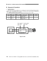
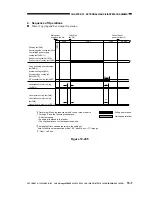
B. Sequence of Operations ......10-6
C. Detecting Errors (E805) .......10-9
III. POWER SUPPLY....................10-10
A. Outline of the Power Supply
System...............................10-10
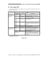
B. Power Supply PCB ............10-11
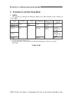
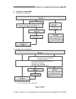
C. Transition to and from Sleep
Mode..................................10-12
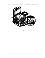
IV. COUNTERS ...........................10-14
A. Outline ...............................10-14
B. Operations of Counters .....10-16
V.
DISASSEMBLY/ASSEMBLY ...10-17
A. External Covers .................10-18
B. Removing the Front
Door/Inside Cover ..............10-20
C. Control Panel .....................10-21
D. DC Controller PCB ............10-23
E. Composite Power Supply
PCB ...................................10-24
F. Low-Voltage Power Supply
PCB ...................................10-24
G. Accessories Power Supply
PCB ...................................10-25
H. Fans ...................................10-25

