COPYRIGHT © 1999 CANON INC. CANON imageRUNNER 400/330 REV.0 JAN. 1999 PRINTED IN JAPAN (IMPRIME AU JAPON)
12-41
CHAPTER 12 INSTALLATION
Caution:
1. For SIZEs 1 through 4, no single size
may be set more than once.
2. The counter reading will remain the
same after the change.
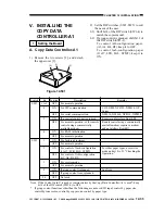
10-3) Conversion Codes
Code
1
2
3
5
7
8
9
10
11
13
15
17
18
19
21
23
24
Size
B5
FOOLS
A4
B4
A3
U SMALL (US)
STMT
U LARGE (UL)
LTR
LGL
LDR (11 x 7)
A5
AFOOLS
A6
FOLIO
COMPUTER
U SMALL 2
Size
Postcard (Jpn)
U LARGE 2
GLTR
10 x 8
GLGL
KLGL
OFFICIO
EOFFICIO
AOFFICIO
BOFFICIO
ALT R
ALGL
12 x 18
B3
A2
17 x 22
18 x 24
Code
25
26
27
28
29
33
35
36
37
38
39
41
48
49
50
51
52
Table 12-506
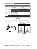
11) Check the DIP switch settings.
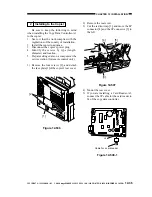
11-1) Shift bit 3 of the DIP switch (SW5-3)
on the copy data controller to OFF.
11-2) Press the / key to indicate the DIP
switch (SW1/SW5) settings.
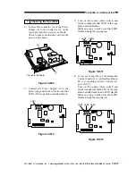
Figure 12-518
11-3) Check the DIP switch (SW1/SW5)
settings of the copy data controller.
(See Table 3-1.)
If the setting is not correct, go back to
"Setting the Board," and repeat the
steps.
If you are setting the Interface Board-B1,
Interface Board-A1, or Communications
Board-A1 as an option, see its respective
Installation Processor.
11-4) Press the switch SW2.
Figure 12-519
S1
S5
SW1-1
SW1-2
SW1-3
SW1-4
SW1-5
SW1-6
SW5-1
SW5-2
SW5-3
SW5-4
SW5-5
SW5-6
: The bit is at ON.
: The bit is at OFF.
SW2
1
6
SW4
SW1 ON
SW5 ON
LED6
LED5
LED4
LED3
LED2
LED1
SW2
SW3
JB2
JB1
JA1
JA2
EPROM
SRAM
CPU
IPC
JC9
JC6
JC5
JC8
J5
1
6
SW5-3
1
6


