COPYRIGHT © 1999 CANON INC. CANON imageRUNNER 400/330 REV.0 JAN. 1999 PRINTED IN JAPAN (IMPRIME AU JAPON)
10-1
CHAPTER 10 EXTERNALS/AUXILIARY MECHANISMS
I. CONTROL PANEL
A. Outline
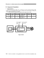
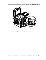
The machine's control panel consists of the PCBs shown in Figure 10-101 and a liquid crystal
display (LCD) capable of showing images in 320 x 240 dots. The control panel has the following
functions:
[1] Data communication
[2] LCD processing
[3] LCD contrast adjustment
[4] Touch switch input processing
Figure 10-101
Image processor PCB
Control panel CPU PCB
Control panel
inverter PCB
LCD panel
Keypad PCB
LCD contrast
adjustment PCB
Control panel
power switch PCB
Function key PCB
Control
panel
IP-CPU
Fax one-touch key
open/closed
detection PCB
Download PCB
Control panel CPU
Main
power supply lamp

