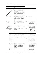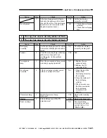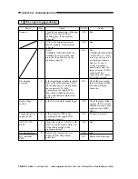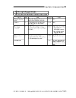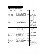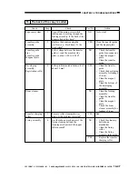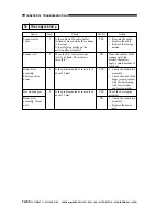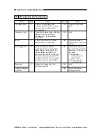
CHAPTER 14 TROUBLESHOOTING
14-54
COPYRIGHT © 1999 CANON INC. CANON imageRUNNER 400/330 REV.0 JAN. 1999 PRINTED IN JAPAN (IMPRIME AU JAPON)
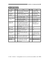
Cause
Scanning lamp
Margin
Drum
Primary charging
assembly
Mirror
DC controller
PCB
Composite power
supply PCB
Image processor
PCB
CCD unit
Action
See "The scanning lamp
fails to turn on."
Go to step 6.
Go to step 3.
Correct the mounting.
Correct the connection.
Go to step 7.
Replace the DC
controller PCB.
Replace the composite
power supply PCB.
Replace the image
processor PCB.
Check the wiring of the
flat cable; if normal,
replace the CCD unit.
Step
1
2
3
4
5
6
7
Yes/No
NO
YES
NO
NO
NO
NO
NO
YES
NO
YES
Check
Does the scanning lamp remain on
during copying operation?
Is there a margin on copies made
normally?
Is the drum set correctly? (Is it
fully pushed in?)
Are the connection and continuity
(connectors and harness) from
J205-3 on the composite power
supply PC to the primary charging
assembly normal? (The resistance
on the primary charging high-
voltage cord must be about 10 K
Ω
.)
Generate test prints (1 through 8 of
PG>TYPE). Is the image on the
photosensitive drum normal?
Is the output (HVPDC*) of J103-
B4 (+) of the DC controller PCB 0
V during copying operation?
Execute FUNCTION>MISC-P>IP-
CHK in service mode. Does it end
in 'OK'?
22 The copy is solid black.

