COPYRIGHT © 1999 CANON INC. CANON imageRUNNER 400/330 REV.0 JAN. 1999 PRINTED IN JAPAN (IMPRIME AU JAPON)
9-17
CHAPTER 9 FIXING SYSTEM
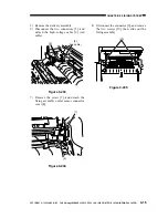
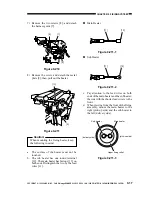
7) Remove the two screws [8], and detach
the harness guide [7].
Figure 9-210
8) Remove the screw, and detach the metal
plate [9]; then, pull out the heater.
Figure 9-211
Caution:
When mounting the fixing heater, keep
the following in mind:
a. The surface of the heater must not be
touched.
b. The sub heater has one round terminal
[12]. The main heater has fastons [13] on
both ends. Distinguish the two by the lead
wires [11].
Figure 9-211-1
n
Sub Heater
Figure 9-211-2
c. Pay attention to the lead wires on both
ends of the main heater and the sub heater:
the side with the shorter lead wire is to the
front.
d. When viewing from the front of the fixing
assembly, mount the main heater to the
right (pick-up side) and the sub heater to
the left (delivery side).
Figure 9-211-3
[8]
[7]
[8]
[10]
[9]
[11]
[13]
[11]
[12]
Main heater
Sub heater
(delivery side)
(pick-up side)
Upper fixing roller
n
Main Heater


