COPYRIGHT © 1999 CANON INC. CANON imageRUNNER 400/330 REV.0 JAN. 1999 PRINTED IN JAPAN (IMPRIME AU JAPON)
14-53
CHAPTER 14 TROUBLESHOOTING
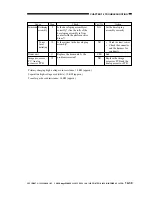
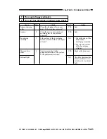
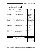
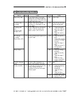
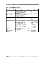
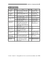
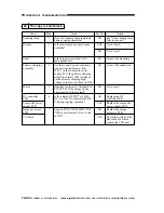
Cause
Developing
assembly
Developing
assembly drive
assembly
Transfer charging
assembly
Transfer high-
voltage cord
DC controller
PCB
DC controller
PCB
Power supply to
CCD PCB
Wiring (CCD
PCB to image
processor PCB)
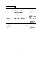
Laser unit
Drum unit
Action
Check the locking
mechanism of the
developing assembly.
Check the drive
mechanism of the
developing assembly.
Go to step 10.
Push the assembly fully
inside the machine.
Check the transfer
charging assembly.
Re-connect it.
Replace the transfer
high-voltage cord.
End.
End.
Check the wiring; if
normal, replace the low-
voltage power supply
PCB.
Re-connect it.
Replace the laser unit.
Replace the drum unit.
Step
1
2
3
4
5
6
7
8
9
10
11
Yes/No
NO
NO
YES
NO
YES
NO
YES
YES
NO
NO
NO
YES
Check
Is the developing assembly locked
to the photosensitive drum during
copying operation?
Is the developing cylinder rotating
during copying operation?
Is the image of test prints (1 through
8 of PG>TYPE) normal?
Is the transfer charging assembly
fully inside the machine?
Is leakage noted in the transfer
charging assembly?
Is the connection of the transfer
high-voltage cord normal? Is there
continuity on the transfer high-
voltage cord? (The resistance of the
transfer high-voltage cord must be
about 10 K
Ω
)
Replace the DC controller PCB. Is
the problem corrected?
Replace the composite power
supply PCB. Is the problem
corrected?
Is there 15 VDC at J304-1 and
about 5 VDC at J304-4 of the CCD
PCB?
Is the connector of the flat cable
locked? Is it inserted correctly?
Turn off the power switch during
development, and slide out the
drum unit. Is the image on the
drum normal?
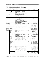
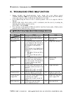
21 The copy is blank.

