COPYRIGHT © 1999 CANON INC. CANON imageRUNNER 400/330 REV.0 JAN. 1999 PRINTED IN JAPAN (IMPRIME AU JAPON)
8-39
CHAPTER 8 PAPER DECK
8. Position of the Deck Pick-Up Roller
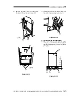
Releasing Solenoid
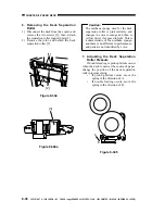
Before removing the deck pick-up roller
releasing solenoid [1] from the support plate,
take note of the positions of the two fixing
screws [2] on the solenoid; or, mark the
position of the solenoid on the support plate
with a scriber.
If you are replacing the solenoid on its
own, be sure to secure it in its initial position.
Figure 8-346
E. Electrical System
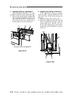
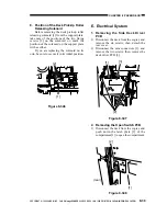
1. Removing the Side Deck Driver
PCB
1) Disconnect the deck from the copier, and
remove the six screws; then, detach the
rear cover.
2) Disconnect the nine connectors [1], and
remove the two screws; then, remove the
deck driver PCB [3].
Figure 8-347
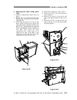
2. Removing the Open Switch PCB
1) Disconnect the deck from the copier, and
push down the latch plate [2] of the
compartment [1] to open the compartment.
Figure 8-348
[1]
[2]
[1]
[3]
[2]
(rear)
[2]
[1]

