COPYRIGHT © 1999 CANON INC. CANON imageRUNNER 400/330 REV.0 JAN. 1999 PRINTED IN JAPAN (IMPRIME AU JAPON)
12-45
CHAPTER 12 INSTALLATION
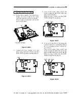
9) Remove the slack from the cable between
the copier an the controller; keep the extra
lengths on the controller by securing them
with a harness band [14].
Figure 12-607
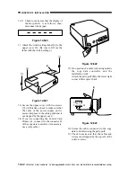
10) Shift the bit of the DIP switch (SW2-4)
[15] on the board of the controller to ON
(to select IPC mode for communication
between copier and controller).
Figure 12-608
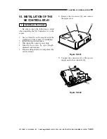
11) If IC6 [16] is mounted on the board of the
controller, shift bit 7 of the DIP switch
(SW2-7) [17] to ON; otherwise, shift it to
OFF.
Note 1: If IC6 [16] is not mounted, you need
not mount it newly.
Note 2: If you are mounting a ROM (IC6)
[16] for upgrading or replacement, be
sure to set bit 7 of the DIP switch
(SW2-7) [17] to ON.
Figure 12-609
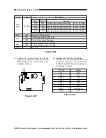
12) Se each bit of the DI switch (SW3) [18] on
the board of the controller as shown.
Figure 12-610
[14]
LED1 LED2 LED3
2
1
LED5
LED6
LED4
IC6
SW1
SW4
SW3
6
1
BAT1
CN4
1
2
CN3
CN2
12345678
[15]
SW2
LED1 LED2 LED3
2
1
LED5
LED6
LED4
IC6
SW1
SW4
SW3
6
1
BAT1
CN4
1
2
CN3
CN2
12345678
SW2
[16]
[17]
LED1 LED2 LED3
2
1
LED5
LED6
LED4
IC6
SW1
SW4
SW3
6
1
BAT1
CN4
1
2
CN3
CN2
SW2
123456
[18]

