CHAPTER 6 IMAGE FORMATION SYSTEM
6-18
COPYRIGHT © 1999 CANON INC. CANON imageRUNNER 400/330 REV.0 JAN. 1999 PRINTED IN JAPAN (IMPRIME AU JAPON)
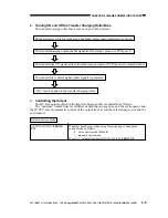
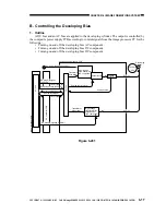
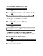
2. Turning On and Off the Developing Bias DC Component
The DC bias ON signal from the image processor PCB goes '0'.
The PW-CPU of the composite power supply PCB generates the bias control (pulse) signal.
The output of the high-voltage main transformer is applied to the developing cylinder.
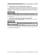
3. Turning On and Off the Developing Bias AC Component
The developing bias AC component is controlled as follows:
The AC bias ON signal from the image processor PCB goes '0'.
The AC component transformer is turned on.
An AC component is added to the developing bias DC component, and the result is applied:
AC component amplitude Vpp = 800 V
AC component frequency Vf = 1840 Hz
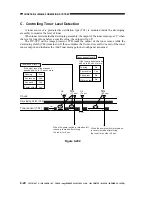
4. Controlling the Developing Bias DC Component to Constant Voltage
The output of the DC bias is controlled by the DC bias control signal from the PW-CPU as
follows:
The output voltage of the DC bias is returned to the PW-CPU.
The pulse width of the DC control signal is varied as necessary according to the return voltage.
The DC bias is maintained to a specific voltage.


