CHAPTER 7 PICK-UP/FEEDING SYSTEM
7-16
COPYRIGHT © 1999 CANON INC. CANON imageRUNNER 400/330 REV.0 JAN. 1999 PRINTED IN JAPAN (IMPRIME AU JAPON)
C. Operation in Standby State
The machine operates as follows when the cassette is slid into or out of the machine:
1. Moving Up the Lifter and Moving Down the Pick-Up Roller Shaft (cassette slid in)
a. Moving Down the Pick-Up Roller Shaft
When the cassette is slid in while the main power is on, the pick-up roller shaft moves down
until it comes into contact with the stack of paper:
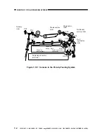
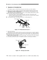
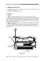
The rear end of the cassette mechanically pushes in the lever 1 of the pick-up unit.
When the cassette size sensor turns on, the main motor (M1) and the pick-up solenoid
(SL1) turn on to swing the pick-up lever.
n
The pick-up roller shaft is controlled by the lever 1 and the pick-up lever.
Figure 7-116 Movement of the Lever 1
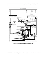
b. Moving Up the Lifter
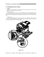
When the main power is turned on while the cassette is set or the cassette is set while in standby
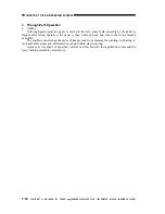
state, the pick-up roller shaft moves down to push down the lifter trigger lever. When the pick-up
roller shaft pushes in the end of the lifter trigger lever, the cam is released, and the lifter moves up
by the drive of the main motor (M1).
When the pick-up roller shaft in contact with the surface of the stack has moved to a specific
level, the pick-up roller shaft returns to its uppermost position to end moving up the lifter.
Figure 7-117 Moving Up the Lifter
Pick-up roller shaft
Lever 1
Feeding roller
Cassette
Pick-up roller
M1
Pick-up roller shaft
Lifter trigger lever
Cam

