COPYRIGHT © 1999 CANON INC. CANON imageRUNNER 400/330 REV.0 JAN. 1999 PRINTED IN JAPAN (IMPRIME AU JAPON)
2-3
CHAPTER 2 BASIC OPERATION PROVIDES
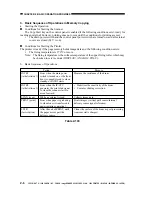
Name
CPU
ROM
Description
Monitors key inputs, Controls the buzzer sound, Controls LCD
activation
b. Control Panel
c. Composite Power Supply PCB
Name
CPU
Description
Controls high voltage; Detects the sate of the front door (open/closed;
Supplies power to the fluorescent lamp; Controls the drum film
thickness detection; Controls transfer; Controls power to the loads
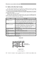
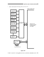
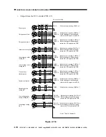
Figure 2-102
IP-CPU*
DC-CPU*
GA
IPC
Feeder
Copy data
controller
Finisher
DIMM(IP*)
4MB
DIMM(DC*)
1MB
DC controller PCB
Image processor
PCB
Paper deck
pedestal
Cassette
pedestal
Laser scanner
motor
DC loads
Control panel
CPU
*If IP, for the image processor; if DC, for the DC controller.
**A separate power supply is used for supplying low-voltage
(other than 24 V).
Multi Output
Tray 3
Main motor
CPU
HVT circuit
DC power
supply**
Lamp
regulator
+24VU
+24VR
Composite power
supply PCB

