CHAPTER 12 INSTALLATION
12-42
COPYRIGHT © 1999 CANON INC. CANON imageRUNNER 400/330 REV.0 JAN. 1999 PRINTED IN JAPAN (IMPRIME AU JAPON)
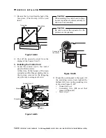
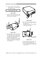
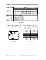
11-5) Check to make sure that the display of
the Keypad-A1 is as follows; then,
disconnect the keypad.
Figure 12-520
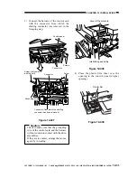
1) Attach the switch settings label [6] to the
upper cover [5]. (Be sure to fill out the
label with the switch settings.)
Figure 12-521
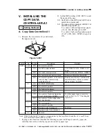
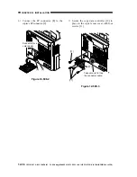
13) Secure the upper cover with two screws
[7]. (At this time, check to make sure that
the cable of the power supply unit is
secured in place to the cable guide and is
not trapped by the upper cover.)
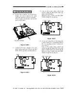
14) If you are connecting the Control Card
Printer A-1, connect it to the connector J4
of the copy data controller. (As necessary,
use a relay cable.)
Figure 12-522
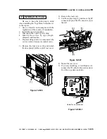
15) If no portion of a cable is showing outside
the copy data controller, end the
installation work.
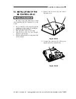
Attach the petty-pull [8] to the lower right
corner of the copier's back.
Figure 12-523
16) Secure the cable connected to the copy
data controller using the petty-pull.
17) Check to make sure that the cables and
wires are not trapped by the copier's or the
sorter's casters.
[7]
[5]
[6]
[7]
J4
Copy Data
Controller-A1
[8]


