CHAPTER 10 EXTERNALS/AUXILIARY MECHANISMS
10-6
COPYRIGHT © 1999 CANON INC. CANON imageRUNNER 400/330 REV.0 JAN. 1999 PRINTED IN JAPAN (IMPRIME AU JAPON)
B. Sequence of Operations
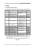
1. 2-Speed Control
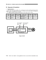
Of the fans used in the machine, some are designed to rotate at half speed during standby
(Tables 10-201, -202 through -204). The speed is switched between full and half by changing the
voltage supplied by the DC-CPU* to the fans.
* CPU for the DC controller circuit (mounted on the image processor PCB).
Speed
Full
Half
PORT B
0
1
Timing
Copying
Stanby
Supply source
Composite power
supply PCB
Low-voltage power
supply PCB
PORT A
1
0
Supply voltage
+24V
+15V
Figure 10-204
DC-CPU
Image processor
PCB
Voltage switching
circuit
From composite
power supply
+24V
From low-voltage
power supply
+15V
DC controller PCB
PORT A
PORT B
FM-LCK
24V or 15V
0V


