CHAPTER 12 INSTALLATION
12-30
COPYRIGHT © 1999 CANON INC. CANON imageRUNNER 400/330 REV.0 JAN. 1999 PRINTED IN JAPAN (IMPRIME AU JAPON)
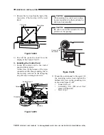
3) Remove the tie-wrap from the back of the
face plate. (The tie-wrap will be used
later.)
Figure 12-404
4) Peel off the protective sheet from the
display of the Control Card V.
3. Installing the Control Card
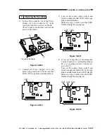
1) Secure the control card to the control
panel with four screws.
At this time, fit the harness of the 4-pin
connector and the blue grounding wire in
the tie-wrap removed in the foregoing
step. (Be sure to arrange as shown.)
Figure 12-405
Caution:
When securing the control card in place,
be sure to position it so that a cad may be
slid in and out smoothly.
Caution:
Be sure to center the connector for the
printer over the opening.
Figure 12-406
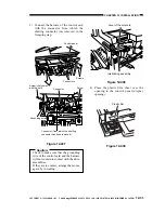
2) Mount the control panel to the copier. Of
the mounting screws used, tighten the
farthest left screw on the grounding wire
as shown in Figure 12-407.
Connector (4 pc.)
Grounding wire (M4 screw that
comes with the unit)
Screw (4 pc.)
Face plate
Tie-wrap
10cm
Screws
Screw
Tie-wrap
Control Card V
Grounding wire
Harness
Connector for
the printer.


