COPYRIGHT © 1999 CANON INC. CANON imageRUNNER 400/330 REV.0 JAN. 1999 PRINTED IN JAPAN (IMPRIME AU JAPON)
7-1
CHAPTER 7 PICK-UP/FEEDING SYSTEM
I. OUTLINE OF OPERATIONS
A. Outline
The machine's pick-up/feeding system consists of the upper/lower cassette and the
multifeeder, and it uses a center reference method, in which paper is moved in the middle of the
pick-up path.
Paper picked up from the cassette or the multifeeder is controlled by the registration roller so
that its leading edge matches the image on the photosensitive drum, and is sent to the copy tray
through the transfer, separation, feeding, and fixing assemblies.
As many as 13 sensors are used to monitor the movement of paper, and 11 sensors are used to
detect jams.
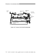
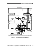
Figure 7-101 shows the arrangement of sensors (input parts), while Figure 7-102 shows
clutches and solenoids (output parts). (These figures are conceptual diagrams, and omit the cassette
drive system.)
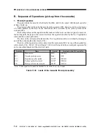
Notation
PS3
PS4
PS6
PS7
PS8
PS9
PS10
PS11
PS18
PS19
PS40
Q1604
Q1605
Name
Multifeeder paper sensor
Pre-registration paper sensor
Reversal assembly inlet sensor
Delivery sensor
Duplexing assembly inlet paper
sensor
Re-pick up paper sensor
Horizontal registration sensor
Vertical path paper sensor
Pick-up sensor 1
Pick-up sensor 2
Fixing assembly outlet sensor
Cassette 1 paper sensor
Cassette 2 paper sensor
Signal
PS3S
PS4S
PS6S
PS7S
PS8S
PS9S
PS10S
PS11S
PS18S
PS19S
PS40S
UCSPD
LCSPD
Pin No.*
J108-B17
J108-B11
J106-2
J107-2
J114-B2
J114-B5
J114-B8
J108-B8
J108-A17
J108-A18
J114-A2
J108-A10
J108-A11
* Pin No. of the signal line on the DC controller PCB.
Table 7-101 Sensors in the Pick-Up/Feeding System

