COPYRIGHT © 1999 CANON INC. CANON imageRUNNER 400/330 REV.0 JAN. 1999 PRINTED IN JAPAN (IMPRIME AU JAPON)
9-1
CHAPTER 9 FIXING SYSTEM
I. OUTLINE OF OPERATIONS
A. Outline
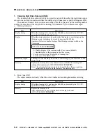
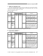
Table 9-101 shows the major functions of the fixing assembly, whileg Figure 9-101 shows the
major parts of the assembly.
Table 9-101 Major Functions of the Fixing Unit
Item
Method
Fixing drive
Fixing heater
Fixing temperature
detection
Cleaner
Protective functions
Error code
Service mode
(major)
Description
Hating roller
Fixing motor (M2)
Main heater:
700 W
Sub heater:600 W
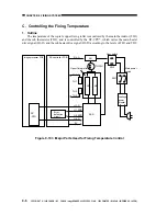
By main thermistor (TH1) and sub thermistor (TH2)
Cleaning belt
good for 160,000 sheets (A4, LTR)
driven by the cleaning belt drive solenoid (SL5)
Activation timing: every time the trailing edge of paper passes through
the fixing roller assembly.
Operations: 3 times for A4/LTR or less (including A4/LTR)
4 times for paper lager than A4/LTR
Error detection is executed by the following, and the power to the fixing heater
is shut down upon detection.
Thermal switch
SSR short circuit
Main thermistor (TH1) temperature
Sub thermistor (TH2) temperature
E000
Main thermistor overheating detection
E001
Sub thermistor overheating/open circuit detection
E002
Fixing temperature failing to reach a specific level
E003
Fixing temperature falling to an abnormal level
E004
SSR short circuit
E005
Absence of the cleaning belt
E014
Fixing motor rotation fault
DISPLAY>ANALOG>
FIX-C
fixing temperature
DISPLAY>
ERROR
error history display
FUNCTION>FIXING>
NIP-CHK
nip measurement
FUNCTION>CLEAR>
ERROR
error initialization
OPTION>BODY>
TEMPCOM2
thick paper temperature control mode switch
OPTION>USER>
WEB-DISP
cleaning belt alarm display switch
COUNTER>MISC>
FIX-WEB
cleaning belt counter reading initialization

