CHAPTER 9 FIXING SYSTEM
9-20
COPYRIGHT © 1999 CANON INC. CANON imageRUNNER 400/330 REV.0 JAN. 1999 PRINTED IN JAPAN (IMPRIME AU JAPON)
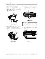
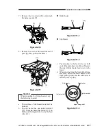
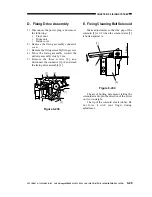
11) Remove the TP screw [20], and pull out
the upper fixing roller.
figure 9-220
12) Lift the lower fixing roller [21] together
with the bearing.
Figure 9-221
n
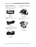
Points to Note When Mounting the Upper
Fixing Roller
1. Be sure to mount the following in the
order indicated: C-ring [1], bias ring [2],
bias insulating plate [3], bearing [4], and
insulating bush [5].
Figure 9-222-1
2. Be sure to keep the roller wrapped in
paper (whenever possible) to protect its
surface against dirt and scratches.
[20]
[21]
[1]
[2]
[4]
[1]
[5]
[3]

