COPYRIGHT © 1999 CANON INC. CANON imageRUNNER 400/330 REV.0 JAN. 1999 PRINTED IN JAPAN (IMPRIME AU JAPON)
9-19
CHAPTER 9 FIXING SYSTEM
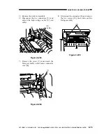
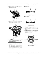
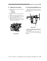
8) Remove one of the screws [12] from the
lower stay; then, fit it in the hole [13] to
release the lower roller.
Figure 9-217-1
Figure 9-217-2
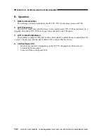
9) Open the separation claw assembly [14],
and mount the protection cover [15] with
a screw [16]; this way, the separation
assembly will remain free.
Figure 9-218
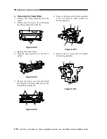
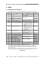
10) Remove the C-ring [17] used to secure the
upper fixing roller in place; then, remove
the gear [18] and the insulating bush [19].
Figure 9-219
[12]
[13]
[15]
[16]
[14]
[17]
[18]
[19]


