CHAPTER 2 BASIC OPERATION PROVIDES
2-2
COPYRIGHT © 1999 CANON INC. CANON imageRUNNER 400/330 REV.0 JAN. 1999 PRINTED IN JAPAN (IMPRIME AU JAPON)
B. Outline of the Electrical Circuitry
The major electrical mechanisms of the machine are controlled by the CPU on the image
processor PCB and the composite power supply PCB. Table 2-101 shows the functions of the
CPUs and those of the ICs associated with the CPU (ROM, RAM).
As many as four types of CPUs are used (for the control panel, image processor, DC controller
PCB, composite power supply PCB); of them, the CPU for the DC controller PCB is mounted on
the image processor PCB.
a. Image Processor PCB (main controller)
The image processor PCB possesses two types of CPUs and two types of flash ROMs and two
RAMs. These CPUs are referred to as the "IP-CPU" (for the image processor circuit) and the "DC-
CPU" (for the DC controller PCB) in terms of function.
* If a single RAM, be sure to use the RAM-A slot.
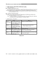
Table 2-101
Name
IP-CPU
(for image processor)
DC-CPU
(for DC controller PCB)
IP, DIMM, Flash ROM,
IP-CPU
DCC, DIMM, Flash ROM,
DC-PC
RAM-A*
(for expansion, 32 MB; J723)
RAM-B*
(for expansion, 32 MB; J723)
Description
Controls the control panel; Controls memory management; Controls
job management; Controls the feeder, DC controller PCB, copy data
controller (accessory) communication; Controls the copy reader and
printer; Controls the printer functions board; controls the fax print,
read, and communication; Controls service and sales mode.
Controls pick-up/feeding; Controls the sorter, Controls fixing;
Controls high-voltage sequence; Controls image formation; Controls
the main motor; Controls the laser scanner motor; Controls the
scanner motor; Detects jams; Detects paper in the cassette; Controls
service mode; Detects the size of originals; Controls IPC
communication
Controls the programs; controls copying; Controls faxing; Controls
control panel messages
Controls the copying sequence program
Retains service mode, user mode, and various parameters; Retains
image memory
Retains service mode, user mode, and various parameters; Retains
image memory
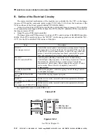
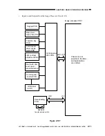
Figure 2-101-1
See VI-I in Chapter 13.
J723
J724
RAM-A
RAM-B
IP,DIMM
DCC,DIMM
1MB
1 MB; top slot
4 MB; bottom slot


