CHAPTER 14 TROUBLESHOOTING
14-96
COPYRIGHT © 1999 CANON INC. CANON imageRUNNER 400/330 REV.0 JAN. 1999 PRINTED IN JAPAN (IMPRIME AU JAPON)
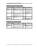
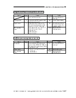
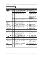
47 The fixing heater fails to turn on.
Cause
SSR
Fixing assembly
DC controller
PCB
Action
See the descriptions for
E000.
Replace the SSR.
End.
Replace the DC
controller PCB.
Step
1
2
3
Yes/No
YES
NO
YES
NO
Check
Is E000 indicated?
Is the continuity between 6 and 7
and between 7 and 8 normal?
Replace the fixing assembly. Is the
problem corrected?
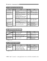
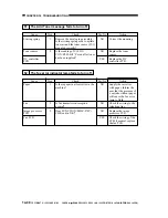
48 The counter fails to operate.
Cause
Counter
DC controller
PCB
Action
Replace the counter.
Check the wiring; if
normal, replace the DC
controller PCB.
Step
1
Yes/No
NO
YES
Check
Turn off the main power switch,
and disconnect the counter
connector (CNT1: J9); then,
measure the resistance on the
counter side. Is it about 480
Ω
?
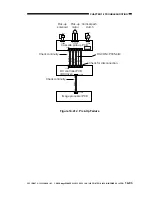
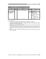
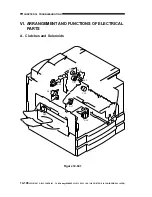
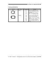
See figure 14-401.
See figure 14-402.
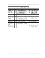
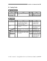
46 The scanning lamp fails to turn on.
Cause
Scanning lamp
Scanning lamp
Connector
Composite power
supply PCB
DC controller
PCB
Image processor
PCB
Action
Replace the scanning
lamp.
Correct the mounting.
Correct the connection.
Replace the composite
power supply PCB.
Replace the DC
controller PCB.
Replace the image
processor PCB.
Step
1
Yes/No
YES
NO
NO
YES
YES
NO
Check
Are both ends of the scanning lamp
blackened?
Is the scanning lamp mounted
correctly?
Are the connectors J90 and J91
connected correctly?
In addition, is the connector J208
on the composite power supply
PCB correct?
Does the voltage between J103-A9
(+) on the DC controller PCB and
GND change when the Copy Start
key is pressed?
Does the voltage between J113-
B12 (+) and GND change when the
Copy Start key is pressed?
See figure 14-409.


