46
Overview of Version 1 Upgrades
Section 1-12
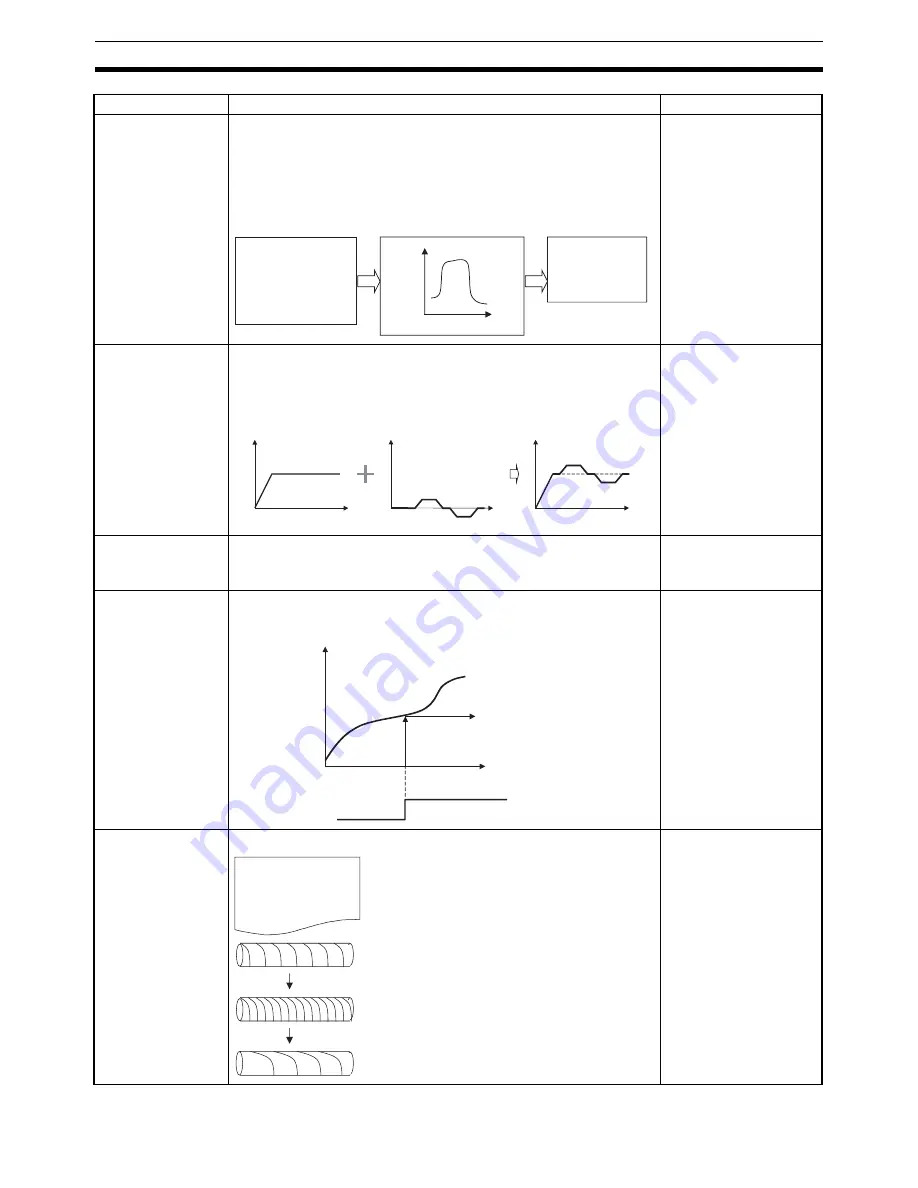
Electronic cam
(CAMBOX)
This function synchronizes the operating axis with the input axis based
on the set cam table.
The following options can be selected for the input axis: Virtual axis
present position, real axis position command value, real axis encoder
feedback input, MPG input, or sync encoder input. There are 720 cam
table points.
Can improve design effi-
ciency because adjust-
ments are simpler than
with mechanical cams.
Note
Electronic
gear (CON-
NECT) and
electronic cam
(CAMBOX)
With an electronic gear (CONNECT) or electronic cam (CAMBOX), the
operating axis can be operated by integrating the operation of another
axis (including a virtual axis) while synchronizing to the input axis.
Operations such as posi-
tion compensation are
enabled by integrating a
virtual axis.
Electronic cam/gear
cancel
(CANCEL)
An electronic gear (CONNECT) or the electronic cam (CAMBOX) can
be cancelled.
Register (REGIST)
(present position
hardware latch)
The present position (encoder) at the leading edge of an external input
can be obtained. The present position is recorded by means of a hard-
ware latch, enabling highly accurate compensation.
Can be used for pur-
poses such as providing
accurate position com-
pensation by means such
as marks printed on film.
Linked traverse
G32 commands can be linked across multiple blocks (line numbers).
The winding width, num-
ber of windings, and pitch
can be set for individual
layers, enabling complex
traverse control.
Function
Summary and features
Advantages
Oper
ating axis
Input axis
•
Virtual axis present posi-
tion
•
Real axis position com-
mand value
•
Real axis encoder feed-
back input
•
MPG or sync encoder in-
put
Input axis
Operating axis
•
Feed axis
•
Cutter
position, etc.
Speed
Speed
Speed
Integrate
Time
Time
Time
X axis (real axis)
Y axis (virtual axis)
Z axis (real axis)
Present position
External inputs
Present position saved to
position data address.
Time
G language program
G32 (TRAVERSE) Xa ...
G32 (TRAVERSE) Xb ...
G32 (TRAVERSE) Xc ...
Linked operation
Linked operation
G32 (TRAVERSE): Wind at pitch a.
G32 (TRAVERSE): Wind at pitch b.
G32 (TRAVERSE): Wind at pitch c.
Summary of Contents for CS1W-MC221 -
Page 1: ...Motion Control Units Cat No W359 E1 04 CS1W MC221 V1 421 V1 OPERATION MANUAL ...
Page 2: ...CS1W MC221 V1 421 V1 Motion Control Units Operation Manual Revised February 2008 ...
Page 3: ...iv ...
Page 5: ...vi ...
Page 11: ...xii ...
Page 15: ...xvi ...
Page 19: ...xx ...
Page 27: ...xxviii Conformance to EC Directives 6 ...
Page 133: ...106 Installation Section 2 2 2 2 4 Dimensions CS1W MC421 CS1W MC221 ...
Page 173: ...146 Connecting Peripheral Devices Section 2 7 ...
Page 227: ...200 Command Area Section 3 6 ...
Page 351: ...324 Interface Specifics Section 5 4 ...
Page 513: ...486 Absolute Encoder Interface Specifications Section 9 7 ...
Page 575: ...548 Error Log Section 12 6 ...
Page 589: ...562 Performance Appendix A ...
Page 655: ...628 Control Bit Flag Timing Charts Appendix E ...
Page 683: ...656 Origin Search Patterns Appendix F ...
Page 685: ...658 Encoder Divider Rate and Rotation Speed for OMRON Servo Drivers Appendix G ...


