175
System Parameters
Section 3-3
The possible setting ranges of the following parameters depends on the set-
ting of the minimum setting unit.
Axis Mode/Display Unit
Refer to the Data Configuration for System Parameters and
6-20 Unlimited
Feeding
for details on these settings. These parameters determine the unit
that will be used when monitoring the present values. While each axis is con-
trolled by pulses in the MC Unit, the present value is monitored in units that
will display on the peripheral device.
The units available are mm, inches, degrees, and pulses, and the default set-
ting is pulses. When a setting other than pulses is used, change the pulse
range to match the units used for the pulse rate parameter. The units for the
following parameters will change when the display unit setting is changed.
Axis Mode
There are two axis modes: Normal Feed Mode and Unlimited Feed Mode.
• Normal Feed Mode
Enables positioning within the software limits after the origin has been es-
tablished.
• Unlimited Feed Mode
Enables positioning even if the origin has not been established. The soft-
ware limits are not used in this mode. and the present position will be indi-
cated between the negative software limit and the positive software limit
minus the minimum setting unit.
For example, if the minimum setting unit is 0.1, the negative software limit
is 0 and the positive software limit is 360, the present position will be indi-
cated between 0 and 359.9.
Refer to
6-20 Unlimited Feeding
for details.
The default setting is for the Normal Mode.
Rotate Direction
This parameter specifies if forward operation is to be performed or if reverse
operation is to be performed for positive positioning commands (positive volt-
ages). Use this parameter in combination with the encoder polarity parameter.
These parameters can be used to correct wiring mistakes between the MC
Unit and servo driver (encoder wiring or speed reference wiring reversed) or
to change directions without changing the actual connections.
The default setting is for forward operation for positive voltages.
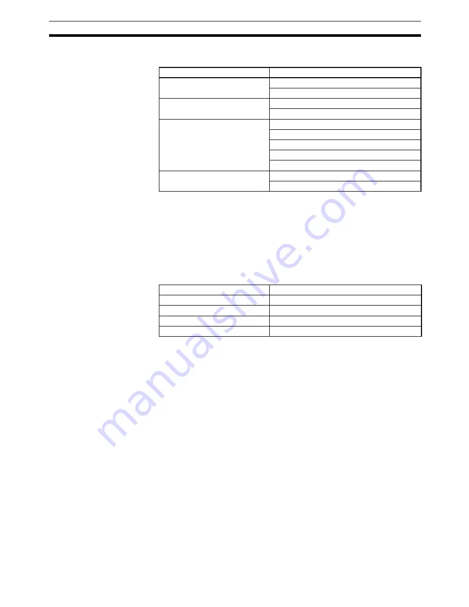
Menu
Parameter
Machine Parameter Edit
Negative software limit
Positive software limit
Coordinate Parameter Edit
Reference origin offset
Workpiece origin offset
Feed Rate Parameter Edit
Maximum feed rate
Max. interpolation feed rate
High-speed origin search feed rate
Low-speed origin search feed rate
Maximum jog feed rate
Zone Parameter Edit
Zone negative SV
Zone positive SV
Menu
Parameter
Machine Parameter Edit
Pulse rate, software limits
Coordinate Parameter Edit
Coordinate system origin offsets
Feed Rate Parameter Edit
All feed rates
Zone Parameter Edit
Zone settings
Summary of Contents for CS1W-MC221 -
Page 1: ...Motion Control Units Cat No W359 E1 04 CS1W MC221 V1 421 V1 OPERATION MANUAL ...
Page 2: ...CS1W MC221 V1 421 V1 Motion Control Units Operation Manual Revised February 2008 ...
Page 3: ...iv ...
Page 5: ...vi ...
Page 11: ...xii ...
Page 15: ...xvi ...
Page 19: ...xx ...
Page 27: ...xxviii Conformance to EC Directives 6 ...
Page 133: ...106 Installation Section 2 2 2 2 4 Dimensions CS1W MC421 CS1W MC221 ...
Page 173: ...146 Connecting Peripheral Devices Section 2 7 ...
Page 227: ...200 Command Area Section 3 6 ...
Page 351: ...324 Interface Specifics Section 5 4 ...
Page 513: ...486 Absolute Encoder Interface Specifications Section 9 7 ...
Page 575: ...548 Error Log Section 12 6 ...
Page 589: ...562 Performance Appendix A ...
Page 655: ...628 Control Bit Flag Timing Charts Appendix E ...
Page 683: ...656 Origin Search Patterns Appendix F ...
Page 685: ...658 Encoder Divider Rate and Rotation Speed for OMRON Servo Drivers Appendix G ...


