56
Overview of Version 1 Upgrades
Section 1-12
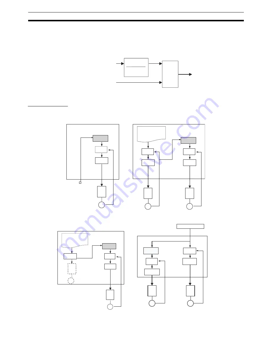
While the electronic gear function is being executed, the gear ratio can be
changed in real time from the G-language program.
It is possible to integrate other axes (i.e., other than the input axis and operat-
ing axis) with the axis that is being operated by the electronic gear. This
enables position compensation according to other axis positions.
Block Diagrams
Gear ratio
numerator
Gear ratio
denominator
Input axis
Integrated axis
Operating axis
Integra-
tion
process-
ing
Note:
The input axis, operating axis, and integrated axis must all be different axes.
Sync Encoder Input
Encoder Input
MC Unit
MC Unit
Electronic gear
(numerator/
denominator)
Position commands
Error
counter
D/A
converter
Speed
references
Sync encoder
Driver
Motor
G-language program
Position commands
Error
counter
D/A
converter
Speed
references
Driver
Motor
Electronic gear
(numerator/
denominator)
Position
commands
Error
counter
D/A
converter
Speed
references
Driver
Motor
Encoder
feedback
Virtual Axis Position Command Input
Real Axis Position Command Input
MC Unit
MC Unit
Position commands
Position
commands
G-language program
Electronic gear
(numerator/
denominator)
G-language program
Virtual axis
(present
position)
Virtual
axis input
Error
counter
D/A
converter
Speed references
Driver
Motor
Electronic gear
(numerator/
denominator)
Error
counter
D/A
converter
Error
counter
D/A
converter
Speed references
Driver
Motor
Encoder
feedback
Position
commands
Speed references
Driver
Motor
Position commands
Summary of Contents for CS1W-MC221 -
Page 1: ...Motion Control Units Cat No W359 E1 04 CS1W MC221 V1 421 V1 OPERATION MANUAL ...
Page 2: ...CS1W MC221 V1 421 V1 Motion Control Units Operation Manual Revised February 2008 ...
Page 3: ...iv ...
Page 5: ...vi ...
Page 11: ...xii ...
Page 15: ...xvi ...
Page 19: ...xx ...
Page 27: ...xxviii Conformance to EC Directives 6 ...
Page 133: ...106 Installation Section 2 2 2 2 4 Dimensions CS1W MC421 CS1W MC221 ...
Page 173: ...146 Connecting Peripheral Devices Section 2 7 ...
Page 227: ...200 Command Area Section 3 6 ...
Page 351: ...324 Interface Specifics Section 5 4 ...
Page 513: ...486 Absolute Encoder Interface Specifications Section 9 7 ...
Page 575: ...548 Error Log Section 12 6 ...
Page 589: ...562 Performance Appendix A ...
Page 655: ...628 Control Bit Flag Timing Charts Appendix E ...
Page 683: ...656 Origin Search Patterns Appendix F ...
Page 685: ...658 Encoder Divider Rate and Rotation Speed for OMRON Servo Drivers Appendix G ...


