


360
Automatic Loading
Section 6-16
Be sure that the program can be compiled by CX-Motion before transferring
the program with automatic loading. Programs that cannot be compiled will
not be transferred.
Explanation
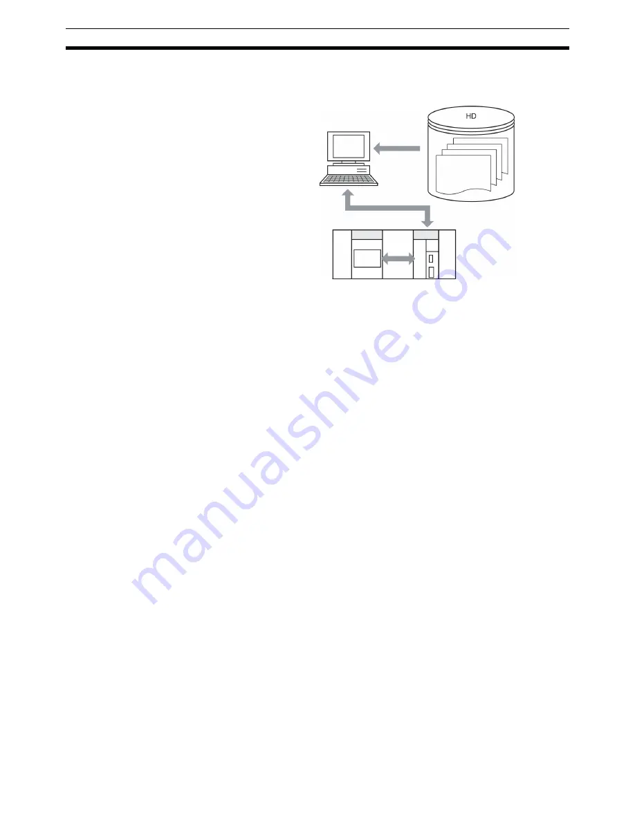
1,2,3...
1.
The MC Unit’s job number is always monitored by CX-Motion.
2.
Using the IOWR instruction, a new job number is written to the job number
currently in the MC Unit.
3.
When CX-Motion detects the specified job number, the program and posi-
tion data are downloaded to the MC Unit from the file for that job number
created by CX-Motion.
4.
Before downloading the program and position data, CX-Motion deletes
from the MC Unit all of the programs for all tasks. Then it downloads the
program and position data for the specified job number.
5.
When the downloading has been completed, the CPU Unit is notified from
the MC Unit. While the program and position are being downloaded, the
Autoloading Bit in the PLC Interface Area turns from OFF to ON, and when
the downloading is completed normally it turns from ON to OFF.
6-16-1 Executing Automatic Loading
To execute automatic loading, set one of the following addresses for the con-
trol code (C) of the IOWR instruction and then transfer the job number to the
MC Unit.
For details on the Command Area, refer to
3-6 Command Area
. For details on
IOWR instruction specifications, refer to
SECTION 4 Data Transfer and Stor-
age
.
Personal computer running CX-Motion
Job No. X
Job No. 3
Job No. 2
Job No. 1
<Program>
P000, P001...
<Position Data>
POSIT...
Job No.
MC Unit
CPU Unit
1., 3., 4.
2., 5.
Summary of Contents for CS1W-MC221 -
Page 1: ...Motion Control Units Cat No W359 E1 04 CS1W MC221 V1 421 V1 OPERATION MANUAL ...
Page 2: ...CS1W MC221 V1 421 V1 Motion Control Units Operation Manual Revised February 2008 ...
Page 3: ...iv ...
Page 5: ...vi ...
Page 11: ...xii ...
Page 15: ...xvi ...
Page 19: ...xx ...
Page 27: ...xxviii Conformance to EC Directives 6 ...
Page 133: ...106 Installation Section 2 2 2 2 4 Dimensions CS1W MC421 CS1W MC221 ...
Page 173: ...146 Connecting Peripheral Devices Section 2 7 ...
Page 227: ...200 Command Area Section 3 6 ...
Page 351: ...324 Interface Specifics Section 5 4 ...
Page 513: ...486 Absolute Encoder Interface Specifications Section 9 7 ...
Page 575: ...548 Error Log Section 12 6 ...
Page 589: ...562 Performance Appendix A ...
Page 655: ...628 Control Bit Flag Timing Charts Appendix E ...
Page 683: ...656 Origin Search Patterns Appendix F ...
Page 685: ...658 Encoder Divider Rate and Rotation Speed for OMRON Servo Drivers Appendix G ...


