433
M Code Outputs
Section 7-4
6.
The program ends in block N004.
7-4-2
M Code Data
There are some M codes that interlock as explained on the previous page,
and others that do not interlock. These differences are explained below.
When an M code is specified in a register or position data address, the speci-
fied value will be rounded to the nearest integer value. An error will occur if the
result is not an acceptable M code value (0 to 999).
M Codes 0 to 499
M codes 0 to 499 are used to interlock with external devices. Execution of the
program is paused when there is not an M code reset input.
M Codes 500 to 999
Use M codes 500 to 999 when it is not necessary to interlock. These M codes
are just output and the program is executed without waiting for an M code
reset input.
These M codes are cleared when the PROGRAM END command (G79) is
executed.
7-4-3
M Code Examples
M codes can be used independently or with G codes, such as G00 and G01,
that execute axis operations.
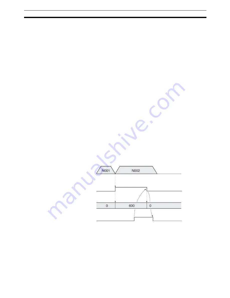
Example
The following program just outputs M code 600. (M codes over 499 do not
interlock.)
N000
P000
X
N001
G01
X100
F100
M600
N002
G01
X200
F100
N003
G79
7-4-4
Effect of Mode Changes on M Code Resets
The status of M codes is not affected by switching from manual to automatic
mode or vice versa.
7-4-5
Clearing M000 to M499 with Forced Block End or G74
The M strobe and M code outputs for M codes 000 to 499 will be cleared if the
program block that outputs the M code is cleared with the Forced Block End
Bit (PLC Interface Area) or the OPTIONAL END (G74) command.
X-axis operation
MC Unit
M Strobe
M Code
Command
from the
CPU Unit
M Code Reset
Block N002 is executed immediately,
without waiting for the M Code Reset
input.
Summary of Contents for CS1W-MC221 -
Page 1: ...Motion Control Units Cat No W359 E1 04 CS1W MC221 V1 421 V1 OPERATION MANUAL ...
Page 2: ...CS1W MC221 V1 421 V1 Motion Control Units Operation Manual Revised February 2008 ...
Page 3: ...iv ...
Page 5: ...vi ...
Page 11: ...xii ...
Page 15: ...xvi ...
Page 19: ...xx ...
Page 27: ...xxviii Conformance to EC Directives 6 ...
Page 133: ...106 Installation Section 2 2 2 2 4 Dimensions CS1W MC421 CS1W MC221 ...
Page 173: ...146 Connecting Peripheral Devices Section 2 7 ...
Page 227: ...200 Command Area Section 3 6 ...
Page 351: ...324 Interface Specifics Section 5 4 ...
Page 513: ...486 Absolute Encoder Interface Specifications Section 9 7 ...
Page 575: ...548 Error Log Section 12 6 ...
Page 589: ...562 Performance Appendix A ...
Page 655: ...628 Control Bit Flag Timing Charts Appendix E ...
Page 683: ...656 Origin Search Patterns Appendix F ...
Page 685: ...658 Encoder Divider Rate and Rotation Speed for OMRON Servo Drivers Appendix G ...


