


85
Overview of Version 1 Upgrades
Section 1-12
2) Programming in G
Language
Format
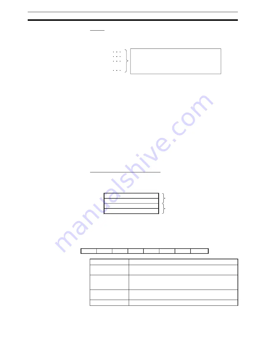
The format is as follows:
Overall format
Note
Block numbers are arbitrary. Operands have been omitted.
Internal Instruction Format
G32_X or Z<windings (rotations) per layer/pitch> (See note 1.)
_Y or U<winding width>
_F<rotational speed> (See note 2.)
[_M<M code>][/stopover] (See note 2.)
[_D<D code>][/stopover] (See note 2.)
[_O<end specification>]
_L<layers>
Note
(1) When the pitch (i.e., the travel distance of the traverse axis for a 360-de-
gree turn of the rotating axis) can be specified for the X or Z axis, 0 cannot
be specified and the upper limit of the winding width is 745654.
(2) F, M, and D are valid only in the first block.
Parameters for Traverse Operation
When the linked traverse function is enabled, position data A1990 to A1993
are used as parameters for the traverse operation. These parameters are
read for the first block with a linked G32 command.
Traverse Operating Mode Specification (A1990/A1992) Details
Different aspects of the operating mode are specified with the value of each
digit. The decimal place is ignored. An error will occur (number out of range) if
a value that cannot be specified is set.
N001 G32
N002 G32
N003 G32
to
N010 G32
N011 G??
If the linked transverse function is enabled and the same axis
and same direction of rotation are specified for G32 commands
in consecutive blocks, up to 100 blocks can be linked for
execution (excluding comment blocks). All linked blocks are
treated as one block. The F designation and M/D designation in
the first block are the only ones that are valid. The designations
in the other blocks are invalid.
A1990
A1991
A1992
A1993
Traverse operating mode
Start specification
Traverse operating mode
Start specification
For X or Y axis
For Z or U axis
8
7
6
5
4
3
2
A1990/A1992
(8)
(7)
(6)
(5)
(4)
(3)
(2)
(1)
First digit
Setting name
Set values
(1) Customized func-
tion enable
0: Disabled (The normal function is performed.)
1: Enabled
(2) X/Y specification
method
0: Specify the number of windings (rotations) of the rotating
axis per layer (normal setting).
1: Specify the pitch.
(3) With/without start
specification
0: No start specification
1: Start specification
(4) to (8)
Not used.
Summary of Contents for CS1W-MC221 -
Page 1: ...Motion Control Units Cat No W359 E1 04 CS1W MC221 V1 421 V1 OPERATION MANUAL ...
Page 2: ...CS1W MC221 V1 421 V1 Motion Control Units Operation Manual Revised February 2008 ...
Page 3: ...iv ...
Page 5: ...vi ...
Page 11: ...xii ...
Page 15: ...xvi ...
Page 19: ...xx ...
Page 27: ...xxviii Conformance to EC Directives 6 ...
Page 133: ...106 Installation Section 2 2 2 2 4 Dimensions CS1W MC421 CS1W MC221 ...
Page 173: ...146 Connecting Peripheral Devices Section 2 7 ...
Page 227: ...200 Command Area Section 3 6 ...
Page 351: ...324 Interface Specifics Section 5 4 ...
Page 513: ...486 Absolute Encoder Interface Specifications Section 9 7 ...
Page 575: ...548 Error Log Section 12 6 ...
Page 589: ...562 Performance Appendix A ...
Page 655: ...628 Control Bit Flag Timing Charts Appendix E ...
Page 683: ...656 Origin Search Patterns Appendix F ...
Page 685: ...658 Encoder Divider Rate and Rotation Speed for OMRON Servo Drivers Appendix G ...


