131
Wiring
Section 2-3
2.
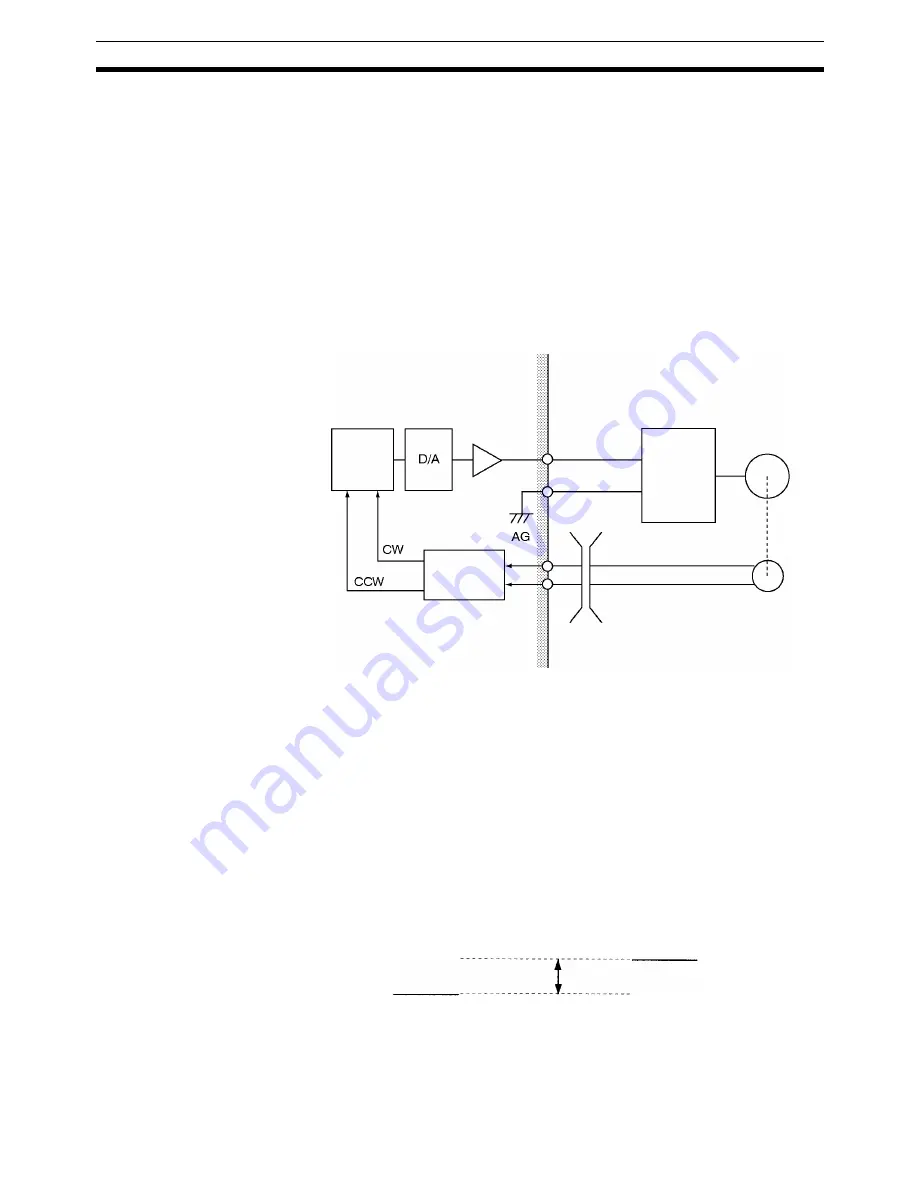
If the phase A and phase B feedback input lines are wired in reverse, the
error counter receives the information as a rotation in the CCW direction.
3.
As a result, the error counter having a count in the CCW direction attempts
to zero the count by outputting a control voltage to the motor driver in the
CW direction.
4.
The servomotor rotates in the CW direction, repeating the above steps
1.
to
3.
Eventually, the motor runs out of control.
Runaway can occur not only from reversed wiring of phases A and B of the
feedback inputs, but also from reversed wiring of the speed control voltage
and the ground lines (crossed dotted lines at 2 in the figure above).
Runaway Due to
Disconnected Wiring
The servomotor runs out of control not only when the position loop is not cor-
rectly formed but also when the position loop is not interrupted due to discon-
nected wiring.
1,2,3...
1.
Wire breakage while the servomotor is rotating:
While the servomotor is rotating, the speed control voltage is not 0 V be-
cause of the signal from the error counter. If the feedback line is broken,
no feedback signals will be given to the error counter and the speed control
voltage remains unchanged from the value existed before the line break-
age, causing motor runaway.
2.
Wire breakage while the motor is stopped:
If the feedback line is broken while the servomotor is stopped and correct
feedback signals cannot be returned, the speed control voltage remains at
zero without changing. Therefore, the servomotor also remains stopped. In
fact, however, the motor may move in one direction without stopping.
This is caused by a discrepancy between the 0 V of the MC Unit’s control volt-
age and the 0 V of the servo driver’s voltage input.
When the two 0 voltages do not match, an electric potential difference is gen-
erated, resulting in a false control voltage. This in turn causes the servomotor
to move in one direction without stopping.
Error
counter
Amp
Direction
discrimination
circuit
Control voltage
Servo
driver
Servomotor
Phase A feedback
Phase B feedback
Encoder
Broken lines
Speed control
voltage (0 V)
Difference in electric
potential
Servo driver
voltage input (0 V)
Summary of Contents for CS1W-MC221 -
Page 1: ...Motion Control Units Cat No W359 E1 04 CS1W MC221 V1 421 V1 OPERATION MANUAL ...
Page 2: ...CS1W MC221 V1 421 V1 Motion Control Units Operation Manual Revised February 2008 ...
Page 3: ...iv ...
Page 5: ...vi ...
Page 11: ...xii ...
Page 15: ...xvi ...
Page 19: ...xx ...
Page 27: ...xxviii Conformance to EC Directives 6 ...
Page 133: ...106 Installation Section 2 2 2 2 4 Dimensions CS1W MC421 CS1W MC221 ...
Page 173: ...146 Connecting Peripheral Devices Section 2 7 ...
Page 227: ...200 Command Area Section 3 6 ...
Page 351: ...324 Interface Specifics Section 5 4 ...
Page 513: ...486 Absolute Encoder Interface Specifications Section 9 7 ...
Page 575: ...548 Error Log Section 12 6 ...
Page 589: ...562 Performance Appendix A ...
Page 655: ...628 Control Bit Flag Timing Charts Appendix E ...
Page 683: ...656 Origin Search Patterns Appendix F ...
Page 685: ...658 Encoder Divider Rate and Rotation Speed for OMRON Servo Drivers Appendix G ...


