


488
Introduction
Section 10-1
10-1 Introduction
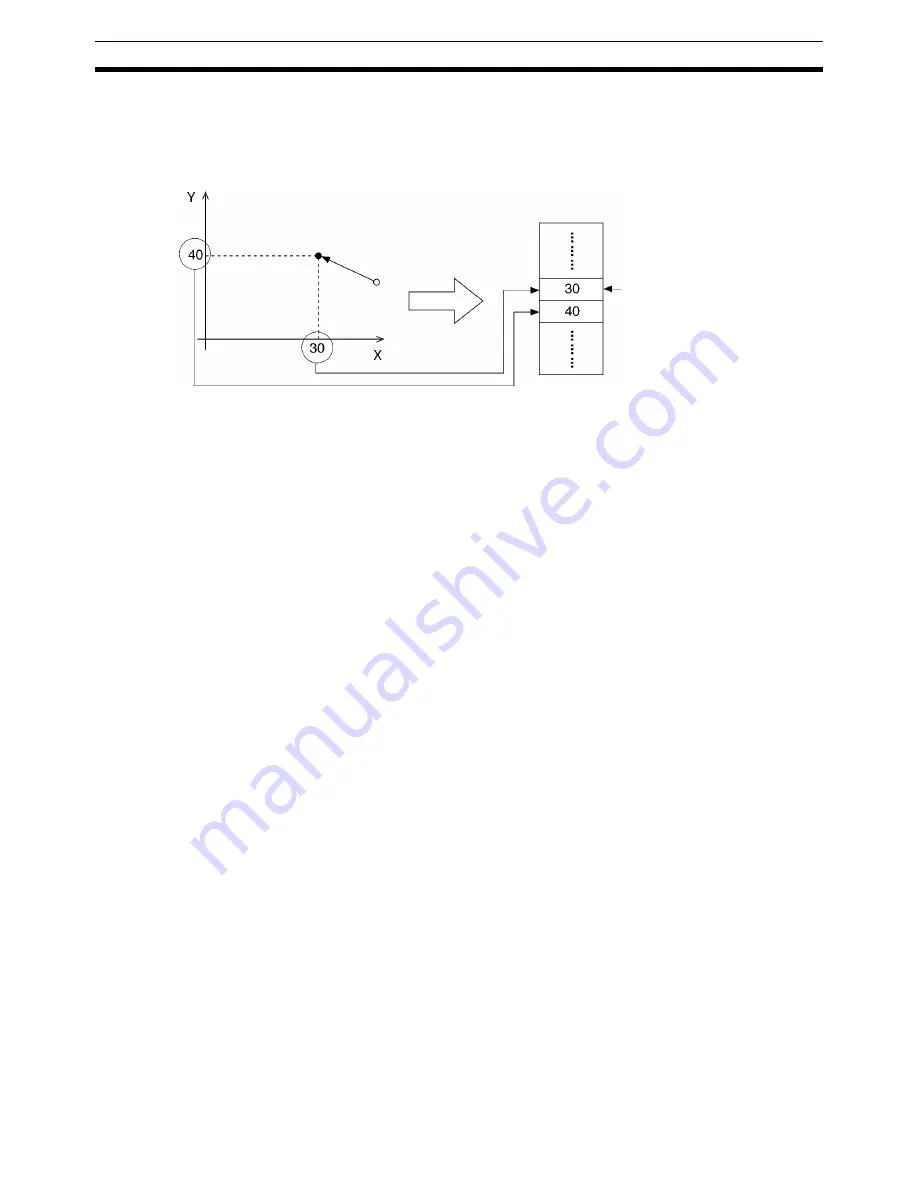
After moving the axes to a desired position, that position can be read to posi-
tion data addresses as position data. This process is known as teaching. The
position data address is called the teaching address.
Teaching is performed separately for each task.
When the teaching command is executed, the present position data for all of
the axes in the task (the axes declared in the Unit Parameter Edit menu) will
be read and stored in the specified teaching addresses in order (X axis first,
then Y axis).
Position Format
Teaching always reads the present position in the reference coordinate sys-
tem. The present position can be read in either of two formats. Refer to
page 278
Types of Teaching
for more details on these formats.
• The target position (reference present position)
• The feedback value (actual present position calculated from the encoder)
Teaching Method
Teaching can be performed in the following two ways:
• From the PLC Interface Area using instructions in the ladder program
• From the Teaching Box
10-1-1 Teaching Addresses
When performing teaching, it is necessary to specify the position data
address where the present position data will be stored. The teaching address
is used to specify this position data address. Teaching addresses are initial-
ized to zero when the power is turned ON or the MC Unit is restarted.
Set the teaching address in the command area when executing teaching from
a ladder program (IOWR instruction), and in the Teaching Box when executing
teaching from the Teaching Box.
10-2 Setting the Teaching Address
To perform teaching, the teaching address must be set to between A0000 and
A1999. The following example shows how to set the teaching address. The
teaching address is set in a memory control parameter in the system parame-
ters.
Set the teaching address in the command area when executing teaching from
the ladder program (IOWR instruction) and in the Teaching Box when execut-
ing teaching from the Teaching Box.
Refer to
3-6 Command Area
for details on the command area.
Teaching addresses
Present position
Move
Teaching
Position Data Area
Summary of Contents for CS1W-MC221 -
Page 1: ...Motion Control Units Cat No W359 E1 04 CS1W MC221 V1 421 V1 OPERATION MANUAL ...
Page 2: ...CS1W MC221 V1 421 V1 Motion Control Units Operation Manual Revised February 2008 ...
Page 3: ...iv ...
Page 5: ...vi ...
Page 11: ...xii ...
Page 15: ...xvi ...
Page 19: ...xx ...
Page 27: ...xxviii Conformance to EC Directives 6 ...
Page 133: ...106 Installation Section 2 2 2 2 4 Dimensions CS1W MC421 CS1W MC221 ...
Page 173: ...146 Connecting Peripheral Devices Section 2 7 ...
Page 227: ...200 Command Area Section 3 6 ...
Page 351: ...324 Interface Specifics Section 5 4 ...
Page 513: ...486 Absolute Encoder Interface Specifications Section 9 7 ...
Page 575: ...548 Error Log Section 12 6 ...
Page 589: ...562 Performance Appendix A ...
Page 655: ...628 Control Bit Flag Timing Charts Appendix E ...
Page 683: ...656 Origin Search Patterns Appendix F ...
Page 685: ...658 Encoder Divider Rate and Rotation Speed for OMRON Servo Drivers Appendix G ...


