


132
Wiring
Section 2-3
In order to prevent this, repair the wiring or adjust the 0 V of either the MC Unit
or the servo driver so that the 0 V levels match, and, to be on the safe side,
implement fail-safe measures in the system.
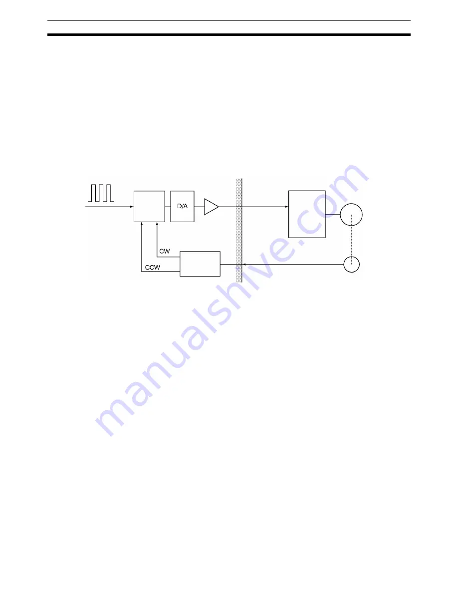
2-3-10 Wiring Check Function
The MC Unit is provided with a wiring check function. This function is
designed to check for reverse wiring and disconnected wiring when the power
supply switch is turned on in order to prevent motor runaway. Whether or not
to a execute wiring check can be determined by setting a system parameter.
For details on troubleshooting when performing the wiring check, refer to
Sec-
tion 2-5 Wiring Check Troubleshooting
.
This function is designed to output a specified number of pulses in the speci-
fied direction and to check whether correct feedback pulses are read.
Set a specified number of test pulses in the error counter. After a set period of
time (the time required for the system parameter to perform wiring check),
check the content of the error counter to determine whether the number of
pulses that were initially set and also the direction are correctly returned.
When the test pulses are set in the CW direction, the feedback pulses corre-
sponding to the set number of pulses will be returned in the CW direction. If
the direction is reversed, it is treated as a reverse wiring error and the servo-
lock is cleared, dropping the voltage output to 0 V.
To correct this faulty wiring, either turn OFF the power and repair the reversed
wiring or change the machine parameter “encoder polarity” from the preset
setting to the opposite setting, i.e., change from “forward rotation for encoder
increase” to “reverse rotation for encoder increase” or from “reverse rotation
for encoder increase” to “forward rotation for encoder increase.”
In addition to the descriptions on the previous page, if the feedback pulses
returned is less than the number of test pulses, a disconnected wiring error
will be generated. Just as with a faulty wiring error, the servolock will be
cleared and the voltage output will drop to 0 V.
To correct a disconnected wiring, turn OFF the power and repair the wiring.
Disconnected wiring errors can also be generated from errors other than wir-
ing errors, such as failure of internal MC Unit components, servo driver errors,
and so on.
Faulty wiring checks and disconnected wiring checks can be carried out
simultaneously. Both checks can be skipped by setting the machine parame-
ter “wiring check” from the MC Support Software to NO. It is initially set to
YES.
The settings for specifying whether a wiring check will be performed, deter-
mining the wiring check time, and specifying the number of pulses, are all
Servomotor
Encoder
Servo
driver
Control
voltage
Phase A/B feedback
Direction
discrimination
circuit
Amp
Error
counter
Test pulses
Summary of Contents for CS1W-MC221 -
Page 1: ...Motion Control Units Cat No W359 E1 04 CS1W MC221 V1 421 V1 OPERATION MANUAL ...
Page 2: ...CS1W MC221 V1 421 V1 Motion Control Units Operation Manual Revised February 2008 ...
Page 3: ...iv ...
Page 5: ...vi ...
Page 11: ...xii ...
Page 15: ...xvi ...
Page 19: ...xx ...
Page 27: ...xxviii Conformance to EC Directives 6 ...
Page 133: ...106 Installation Section 2 2 2 2 4 Dimensions CS1W MC421 CS1W MC221 ...
Page 173: ...146 Connecting Peripheral Devices Section 2 7 ...
Page 227: ...200 Command Area Section 3 6 ...
Page 351: ...324 Interface Specifics Section 5 4 ...
Page 513: ...486 Absolute Encoder Interface Specifications Section 9 7 ...
Page 575: ...548 Error Log Section 12 6 ...
Page 589: ...562 Performance Appendix A ...
Page 655: ...628 Control Bit Flag Timing Charts Appendix E ...
Page 683: ...656 Origin Search Patterns Appendix F ...
Page 685: ...658 Encoder Divider Rate and Rotation Speed for OMRON Servo Drivers Appendix G ...


