332
Helical Circular Interpolation
Section 6-5
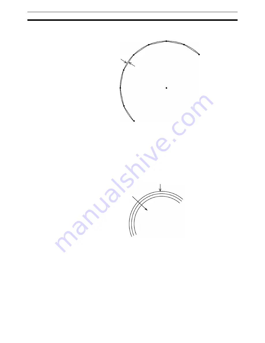
of the locus of actual movements is smaller than the radius of the arc due to
accumulated pulses.
The interpolation acceleration time, the interpolation deceleration time, and
triangular control are the same as for linear interpolation.
Refer to
6-3 Linear Interpolation
for details on interpolation acceleration time,
interpolation deceleration time, and triangular control.
Note
If positioning for circular interpolation is performed at high speed, the radius of
the locus of actual movements will be reduced. This can also be improved by
setting feed forward gain in the servo system. For details, refer to
6-9 Chang-
ing Parameters
.
6-5
Helical Circular Interpolation
Overview
Mode:
Automatic;
Method:
G language (G02, G03)
Helical circular interpolation adds another axis to circular interpolation. It can-
not be used with CS1W-MC221 MC Units. For details on using helical circular
interpolation with the G language, refer to
7-3-3 G02 and G03: CIRCULAR
INTERPOLATION
.
With earlier MC Unit models, helical circular interpolation was limited to a sin-
gle turn, but the CS1W-MC421’s multiturn capability makes helical operations
easier.
Basic Concept
Similar to circular interpolation, helical circular interpolation performs control
operations by dividing a 3-dimensional circular arc in the shape of a polygon.
Arc
Locus of actual movements
End point
Center of a circle
Starting point
Intended locus of arc
The higher the speed of positioning
for circular interpolation is, the
smaller the radius of the locus of
actual movements will be.
Summary of Contents for CS1W-MC221 -
Page 1: ...Motion Control Units Cat No W359 E1 04 CS1W MC221 V1 421 V1 OPERATION MANUAL ...
Page 2: ...CS1W MC221 V1 421 V1 Motion Control Units Operation Manual Revised February 2008 ...
Page 3: ...iv ...
Page 5: ...vi ...
Page 11: ...xii ...
Page 15: ...xvi ...
Page 19: ...xx ...
Page 27: ...xxviii Conformance to EC Directives 6 ...
Page 133: ...106 Installation Section 2 2 2 2 4 Dimensions CS1W MC421 CS1W MC221 ...
Page 173: ...146 Connecting Peripheral Devices Section 2 7 ...
Page 227: ...200 Command Area Section 3 6 ...
Page 351: ...324 Interface Specifics Section 5 4 ...
Page 513: ...486 Absolute Encoder Interface Specifications Section 9 7 ...
Page 575: ...548 Error Log Section 12 6 ...
Page 589: ...562 Performance Appendix A ...
Page 655: ...628 Control Bit Flag Timing Charts Appendix E ...
Page 683: ...656 Origin Search Patterns Appendix F ...
Page 685: ...658 Encoder Divider Rate and Rotation Speed for OMRON Servo Drivers Appendix G ...


