


440
M Code Outputs
Section 7-4
Operating Patterns
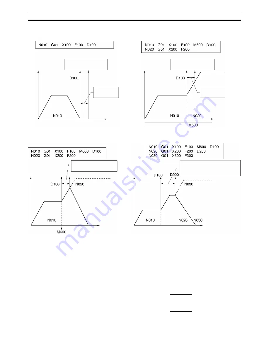
7-4-10 Stopover Function
The Stopover function outputs M code or D code without stopping operation
when the axis is moved a preset amount (judged from the present position) in
axis operation. It is used to control peripheral devices prior to completing a
move and to improve tact time. The function can be used with G codes for all
operations and with either a D code or a M code, but not both at the same
time.
Format
M <M code>/<Stopover> or D <D code>/<Stopover>
Case 1: N010
G01
X200
F200
D100/X100 Outputs D code 100
after moving the axis
100 mm on the X axis.
Case 2: N010
G01
X200
F200
M600/X100 Outputs D code 600
after moving the axis
100 mm on the X axis.
Case 1: Notification after Positioning Is Completed
Case 2: Pass Mode Operation
Speed
Notification of interrupt task
No. 100 to the CPU Unit
Notification
within 0 to 10 ms
Speed
Notification of interrupt task
No. 100 to the CPU Unit
Notification
within 0 to 10 ms
Time
Time
Case 3: CPU Unit Cannot Receive Interrupts during Pass Mode
Case 4: Continuous Interrupt Tasks Initiated
Speed
Decelerates to a stop if output is
not possible within 10 ms
Speed
An error is generated and the axis decelerates to
a stop if the CPU Unit cannot receive interrupts
within a maximum of 10 ms causing competition
between the first and next interrupt notifications in
the same task.
Up to
10 ms
Time
Time
Summary of Contents for CS1W-MC221 -
Page 1: ...Motion Control Units Cat No W359 E1 04 CS1W MC221 V1 421 V1 OPERATION MANUAL ...
Page 2: ...CS1W MC221 V1 421 V1 Motion Control Units Operation Manual Revised February 2008 ...
Page 3: ...iv ...
Page 5: ...vi ...
Page 11: ...xii ...
Page 15: ...xvi ...
Page 19: ...xx ...
Page 27: ...xxviii Conformance to EC Directives 6 ...
Page 133: ...106 Installation Section 2 2 2 2 4 Dimensions CS1W MC421 CS1W MC221 ...
Page 173: ...146 Connecting Peripheral Devices Section 2 7 ...
Page 227: ...200 Command Area Section 3 6 ...
Page 351: ...324 Interface Specifics Section 5 4 ...
Page 513: ...486 Absolute Encoder Interface Specifications Section 9 7 ...
Page 575: ...548 Error Log Section 12 6 ...
Page 589: ...562 Performance Appendix A ...
Page 655: ...628 Control Bit Flag Timing Charts Appendix E ...
Page 683: ...656 Origin Search Patterns Appendix F ...
Page 685: ...658 Encoder Divider Rate and Rotation Speed for OMRON Servo Drivers Appendix G ...


