96
Overview of Version 1 Upgrades
Section 1-12
1,2,3...
1.
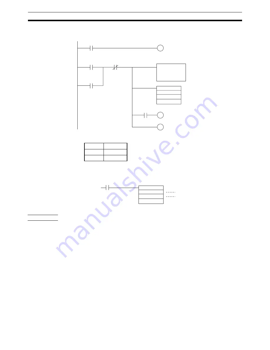
Set in A1999. (Use CX-Motion to set 34231201 directly or set it with the
following ladder program.)
2.
Select the customized functions. See “Customized Functions” on page 45.
3.
Enable output.
Application
Precautions
• The settings in A1999 are read when the IOWR instruction is used to
select the customized functions. Once set, the settings cannot be
changed.
• Changes to the zone parameters are read in real time. The settings in the
negative and positive directions cannot be changed at the same time. If
there is a possibility that unexpected outputs will be produced when a
zone is being changed, turn OFF the General-purpose Output Bits (allo-
cated word n, bits 0 to 3) before changing the zone.
Note
With the CX-Motion, both the positive and negative settings can be down-
loaded at the same time. There are, however, subtle differences in the timing
for reading these at the MC Unit, so the above precaution applies even when
downloading zone settings from the CX-Motion.
• The response time for changing zone parameters and General-purpose
Output Bits (allocated word n, bits 0 to 3) depends on Unit status. Approx-
imately 10 ms is required.
R1
R3
R2
Sets the following
data, with D00000
as the first source
word.
IOWR
#07CF
D00000
#00030000
OUT R2 (Work bit)
OUT R3 (Work bit)
←
A1999
←
Specifies the destination
unit number (0) and the number
of words of data to be transferred (3).
Execution condition
DIFU R1 (Work bit)
=
Transfer Data (DM)
D00000
0000
D00001
1201
D00002
3423
ORW
#000F
2000
2000
Execution condition
Enables general-purpose outputs 1 to 4
For a unit number of 0
Summary of Contents for CS1W-MC221 -
Page 1: ...Motion Control Units Cat No W359 E1 04 CS1W MC221 V1 421 V1 OPERATION MANUAL ...
Page 2: ...CS1W MC221 V1 421 V1 Motion Control Units Operation Manual Revised February 2008 ...
Page 3: ...iv ...
Page 5: ...vi ...
Page 11: ...xii ...
Page 15: ...xvi ...
Page 19: ...xx ...
Page 27: ...xxviii Conformance to EC Directives 6 ...
Page 133: ...106 Installation Section 2 2 2 2 4 Dimensions CS1W MC421 CS1W MC221 ...
Page 173: ...146 Connecting Peripheral Devices Section 2 7 ...
Page 227: ...200 Command Area Section 3 6 ...
Page 351: ...324 Interface Specifics Section 5 4 ...
Page 513: ...486 Absolute Encoder Interface Specifications Section 9 7 ...
Page 575: ...548 Error Log Section 12 6 ...
Page 589: ...562 Performance Appendix A ...
Page 655: ...628 Control Bit Flag Timing Charts Appendix E ...
Page 683: ...656 Origin Search Patterns Appendix F ...
Page 685: ...658 Encoder Divider Rate and Rotation Speed for OMRON Servo Drivers Appendix G ...


