


412
G-language Commands
Section 7-3
Note
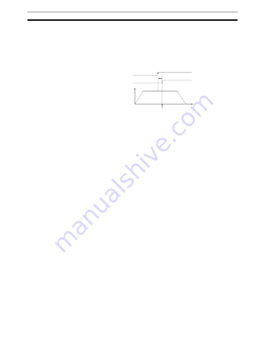
When positioning using interrupt feeding, positions that are determined after
external sensors are enabled will vary depending on various conditions, such
as the ambient temperature. This variation occurs due to detection delays by
external sensors and the general input circuitry of the MC Unit.
The following illustration shows the MC Unit detection delay, and the resulting
variation, assuming that there is no detection delay due to external sensors.
• The external sensor changes from disabled to enabled.
• The status of this external sensor is taken as the general input. There is a
maximum delay of 1 ms in this general input circuit, so the MC Unit starts
positioning control at no more than 1 ms after the external sensor is
enabled.
• Accordingly, the actual position to be determined by the MC Unit after the
external sensor is enabled can be obtained according to the following for-
mula.
Actual travel distance [pulse] =
Specified travel distance [pulse] + Feed rate [pps] x Detection delay [s]
• Actual travel distance refers to the distance from the point where the
external sensor is enabled to the point where the machine actually
stops moving.
• Specified travel distance refers to the distance specified by G31.
• Feed rate refers to the rate specified by G31.
• The detection delay is 0.001 (s) max.
7-3-15 G32: TRAVERSE
This command is provided for traverse, winding machine operations and it can
be used in either Pass Mode or In-position Check OFF Mode.
Format
G32_<Axis movement command>_<Speed reference>
[_M<M code>[/Stopover (Note 1)]]
[_D<D code>[/Stopover (Note 1)]]
[_O<Trailing end specification>](Note 2)
_L<Number of layers>
Note
1.
The stopover function can be used with either an M code or a D code, but
not with both.
2.
When winding at the end, specify the number of layers. Winding will not be
performed at the end if the number of layers is not specified.
T
ON
OFF
External sensor
Disabled
Enabled
T: Detection delay (1 ms max.)
Speed
control
Position
control
Timing for starting actual positioning by the MC Unit.
General input
Summary of Contents for CS1W-MC221 -
Page 1: ...Motion Control Units Cat No W359 E1 04 CS1W MC221 V1 421 V1 OPERATION MANUAL ...
Page 2: ...CS1W MC221 V1 421 V1 Motion Control Units Operation Manual Revised February 2008 ...
Page 3: ...iv ...
Page 5: ...vi ...
Page 11: ...xii ...
Page 15: ...xvi ...
Page 19: ...xx ...
Page 27: ...xxviii Conformance to EC Directives 6 ...
Page 133: ...106 Installation Section 2 2 2 2 4 Dimensions CS1W MC421 CS1W MC221 ...
Page 173: ...146 Connecting Peripheral Devices Section 2 7 ...
Page 227: ...200 Command Area Section 3 6 ...
Page 351: ...324 Interface Specifics Section 5 4 ...
Page 513: ...486 Absolute Encoder Interface Specifications Section 9 7 ...
Page 575: ...548 Error Log Section 12 6 ...
Page 589: ...562 Performance Appendix A ...
Page 655: ...628 Control Bit Flag Timing Charts Appendix E ...
Page 683: ...656 Origin Search Patterns Appendix F ...
Page 685: ...658 Encoder Divider Rate and Rotation Speed for OMRON Servo Drivers Appendix G ...


