129
Wiring
Section 2-3
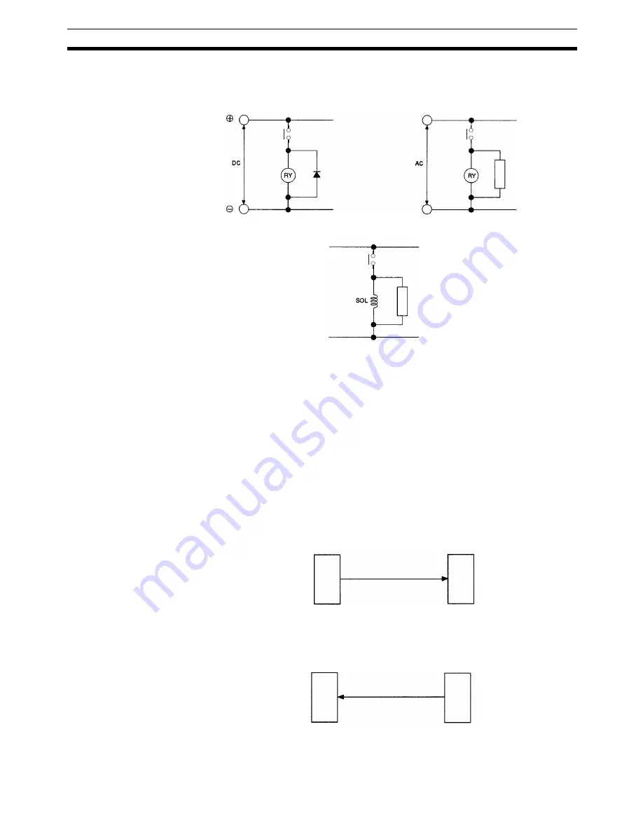
For inductive loads such as relays or solenoid valves, connect surge absorb-
ers.
Note
Connect a surge-absorbing diode or surge absorber close to the relay. Use a
surge-absorbing diode with a voltage tolerance at least five times greater than
the circuit voltage.
Noise may be generated on the power supply line if the same power supply
line is used for an electric welder or electrical discharge unit. Provide an insu-
lating transformer and a line filter in the power supply section to remove such
noise.
It is recommended that twisted-pair cables be used for power supply lines.
Use adequate grounds (i.e., to 100
Ω
or less) with a wire cross section of
2 mm
2
or greater.
Use twisted-pair shielded cables for control voltage output signals, MPG sig-
nals, sync encoder signals, and feedback input signals.
For the control voltage output signals, wire a maximum of 2 m between the
MC Unit and the servo driver.
Wire the distance between the MC Unit and the feedback pulse generator
(i.e., encoder or the servo driver) with a maximum length of 2 m.
Note
The input terminals that operate the 24-V system are isolated with photocou-
plers to reduce external noise effects on the control system. Avoid connec-
Surge-absorbing
diode
Surge absorber
DC Relay
AC Relay
Solenoid
Surge absorber
MC Unit
Voltage output
2 m max.
Servo Driver
MC Unit
2 m max.
Feedback input
Servo driver
or encoder
Line Driver Output
(Line driver output)
Summary of Contents for CS1W-MC221 -
Page 1: ...Motion Control Units Cat No W359 E1 04 CS1W MC221 V1 421 V1 OPERATION MANUAL ...
Page 2: ...CS1W MC221 V1 421 V1 Motion Control Units Operation Manual Revised February 2008 ...
Page 3: ...iv ...
Page 5: ...vi ...
Page 11: ...xii ...
Page 15: ...xvi ...
Page 19: ...xx ...
Page 27: ...xxviii Conformance to EC Directives 6 ...
Page 133: ...106 Installation Section 2 2 2 2 4 Dimensions CS1W MC421 CS1W MC221 ...
Page 173: ...146 Connecting Peripheral Devices Section 2 7 ...
Page 227: ...200 Command Area Section 3 6 ...
Page 351: ...324 Interface Specifics Section 5 4 ...
Page 513: ...486 Absolute Encoder Interface Specifications Section 9 7 ...
Page 575: ...548 Error Log Section 12 6 ...
Page 589: ...562 Performance Appendix A ...
Page 655: ...628 Control Bit Flag Timing Charts Appendix E ...
Page 683: ...656 Origin Search Patterns Appendix F ...
Page 685: ...658 Encoder Divider Rate and Rotation Speed for OMRON Servo Drivers Appendix G ...


