402
G-language Commands
Section 7-3
7-3-9
G26: REFERENCE ORIGIN RETURN
Moves to the reference origin.
Format
G26_<Axis name ... >[_M<M code>[/Stopover (Note.)]]
[_D<D code>[/Stopover (Note.)]]
Note
The stopover function can be used with either an M code or a D code, but not
with both.
Operands
The following table shows the possible settings for the operands.
Note
Refer to
7-4 M Code Outputs
for details on M codes, and to
7-4-9 D Code Out-
puts
for details on D codes. Refer to
7-4-10 Stopover Function
for details on
the stopover function. Refer to
SECTION 9 Establishing the Origin
for details
on origin searches.
Description
This command moves the specified axes to the reference origin by PTP con-
trol. The coordinate system and mode settings will be as follows after the
return to the reference origin:
1,2,3...
1.
The coordinate system will be set to the reference coordinate system.
2.
The command mode will be set to absolute specification.
3.
The operating mode will be set to Pass Mode.
The settings will not be switched to the ones above if the G26 command is ter-
minated while in progress by the OPTIONAL END command (G74), FORCED
BLOCK END, or other command. The command is also considered to be in
progress while waiting for the M code reset.
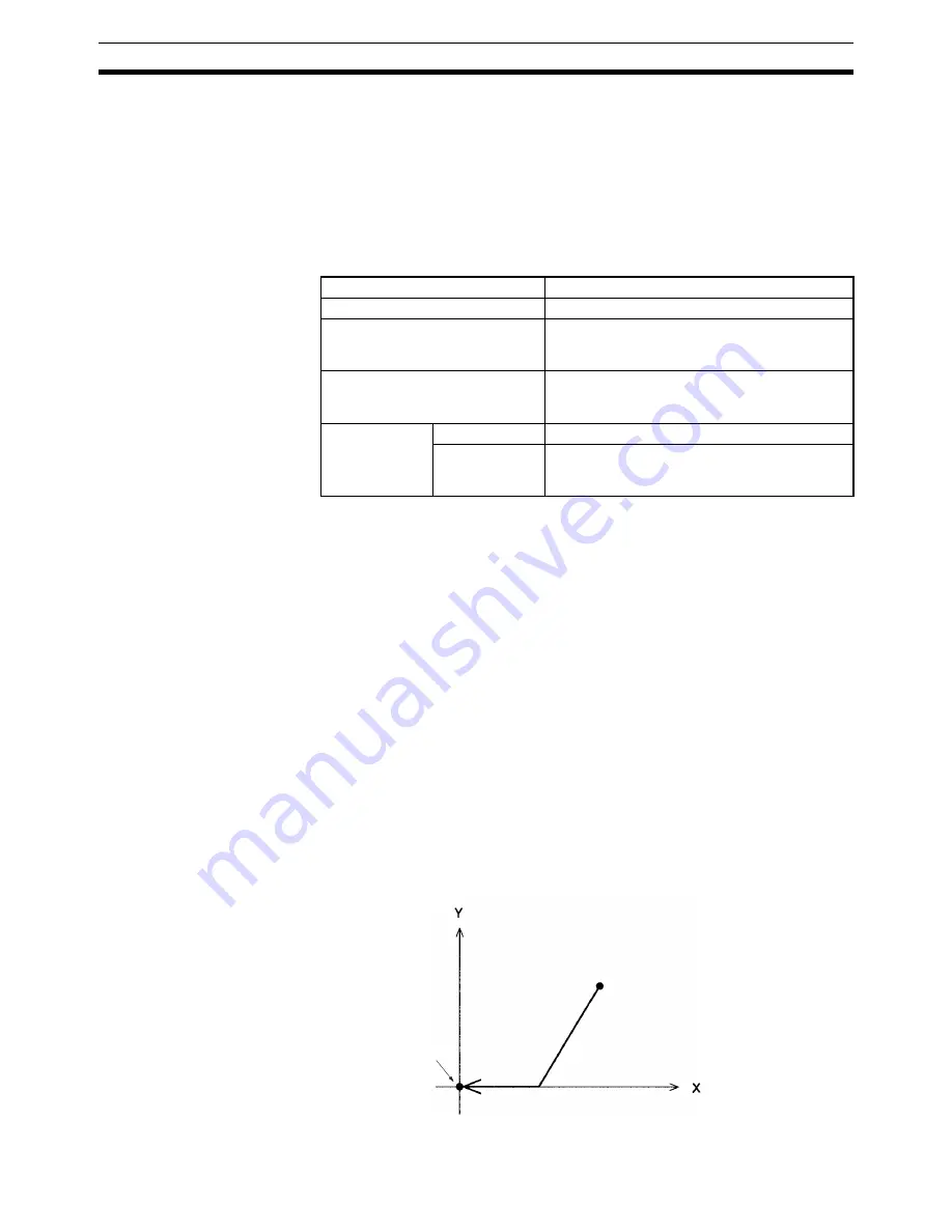
Programming Example
The following example moves the X and Y axes to the reference origin.
:
:
N010
G26
XY
M500
:
:
Operand
Possible settings
Axis names
X, Y, Z, U
M code
000 to 999
(E00) to (E31)
A0000 to A1999
D code
000(0) to 255
(E00) to (E31)
A0000 to A1999
Stopover
Axes
X, Y, Z, U
Coordinate data 0 to 39999999
(E00) to (E31)
A0000 to A1999
Reference origin
Reference coordinate system
The M code (M500)
is output here.
Summary of Contents for CS1W-MC221 -
Page 1: ...Motion Control Units Cat No W359 E1 04 CS1W MC221 V1 421 V1 OPERATION MANUAL ...
Page 2: ...CS1W MC221 V1 421 V1 Motion Control Units Operation Manual Revised February 2008 ...
Page 3: ...iv ...
Page 5: ...vi ...
Page 11: ...xii ...
Page 15: ...xvi ...
Page 19: ...xx ...
Page 27: ...xxviii Conformance to EC Directives 6 ...
Page 133: ...106 Installation Section 2 2 2 2 4 Dimensions CS1W MC421 CS1W MC221 ...
Page 173: ...146 Connecting Peripheral Devices Section 2 7 ...
Page 227: ...200 Command Area Section 3 6 ...
Page 351: ...324 Interface Specifics Section 5 4 ...
Page 513: ...486 Absolute Encoder Interface Specifications Section 9 7 ...
Page 575: ...548 Error Log Section 12 6 ...
Page 589: ...562 Performance Appendix A ...
Page 655: ...628 Control Bit Flag Timing Charts Appendix E ...
Page 683: ...656 Origin Search Patterns Appendix F ...
Page 685: ...658 Encoder Divider Rate and Rotation Speed for OMRON Servo Drivers Appendix G ...


