


329
Linear Interpolation
Section 6-3
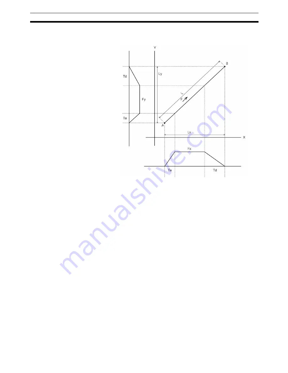
Linear interpolation from the point A to the point B will be as shown below
when using the X and Y axes.
F:
Designated interpolation feed rate
Fx: Interpolation feed rate of the X axis based on F
Fy: Interpolation feed rate of the Y axis based on F
Ta: Interpolation acceleration time
Td: Interpolation deceleration time
Fx and Fy can be expressed as follows:
Fx= Lx/L x F
Fy= Ly/L x F
Where, L is the travel distance in the specified locus, Lx is the travel distance
along the X axis, and Ly is the travel distance along the Y axis.
Interpolation Acceleration
and Deceleration Times
Interpolation acceleration and deceleration times for linear interpolation are
defined as follows:
Interpolation acceleration time: Time required to reach the specified interpo-
lation feed rate on the composite axial locus.
Interpolation deceleration time: Time required until the speed control voltage
drops to zero from the specified interpolation
feed rate on the composite axial locus.
The acceleration time and deceleration time (feed rate parameters) are set
either from the CX-Motion or by using IOWR in the ladder program.
Unlike PTP control, linear interpolation acceleration and deceleration times
are not affected by the speed. Acceleration changes according to the move-
ment to satisfy the preset interpolation acceleration and deceleration times.
Constant Acceleration
Mode
When positioning is executed using linear interpolation, the normal operation
(i.e., the CX-Motion default setting) is for positioning to accelerate at the inter-
polation acceleration time until the specified interpolation feed rate is reached,
and for positioning to decelerate at the interpolation deceleration time. Unlike
Y-axis movements
X-axis movements
Summary of Contents for CS1W-MC221 -
Page 1: ...Motion Control Units Cat No W359 E1 04 CS1W MC221 V1 421 V1 OPERATION MANUAL ...
Page 2: ...CS1W MC221 V1 421 V1 Motion Control Units Operation Manual Revised February 2008 ...
Page 3: ...iv ...
Page 5: ...vi ...
Page 11: ...xii ...
Page 15: ...xvi ...
Page 19: ...xx ...
Page 27: ...xxviii Conformance to EC Directives 6 ...
Page 133: ...106 Installation Section 2 2 2 2 4 Dimensions CS1W MC421 CS1W MC221 ...
Page 173: ...146 Connecting Peripheral Devices Section 2 7 ...
Page 227: ...200 Command Area Section 3 6 ...
Page 351: ...324 Interface Specifics Section 5 4 ...
Page 513: ...486 Absolute Encoder Interface Specifications Section 9 7 ...
Page 575: ...548 Error Log Section 12 6 ...
Page 589: ...562 Performance Appendix A ...
Page 655: ...628 Control Bit Flag Timing Charts Appendix E ...
Page 683: ...656 Origin Search Patterns Appendix F ...
Page 685: ...658 Encoder Divider Rate and Rotation Speed for OMRON Servo Drivers Appendix G ...


