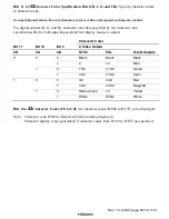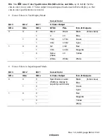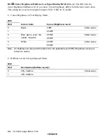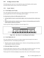
Rev. 1.0, 02/00, page 833 of 1141
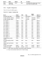
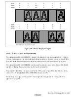
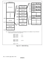
Line number
Data
1
2
3
4
5
6
7
8
9
10
11
12
13
14
15
16
17
18
19
32
F000
F000
F3FC
F3FC
F300
F300
F300
F300
F3F0
F3F0
F300
F300
F300
F300
F300
F300
F000
F000
FFFF
FFFF
11109 8 7 6 5 4 3 2 1
1
2
3
4
5
6
7
8
9
10
11
12
13
14
15
16
17
18
0
Line
12 dots
18 dots
32 words
16 bits
Bit
Unused area
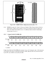
Figure 29.8 OSDROM Data Configuration (for the letter “F”)
Note:
OSDROM consists of 12 dots
×
18 lines per character. When character data is written to
flash memory, addresses are written in a 16-bit
×
32-word area as shown in figure 29.8.
Data in the unused area should be set to 1. In addition, character data for blank display
should always be set to 0.
29.3.7
Display Data RAM (OSDRAM)
8
*
9
*
R/W
10
*
R/W
11
*
12
*
R/W
*
R/W
13
15
BON0
CR
CG
CB
C8
*
R/W
BLNK
14
*
R/W
HT/CR
R/W
R/W
BON1
Bit:
Initial value:
R/W:
0
*
1
*
R/W
2
*
R/W
3
*
4
*
R/W
*
R/W
5
7
C4
C3
C2
C1
C0
*
R/W
C7
6
*
R/W
C6
R/W
R/W
C5
Bit:
Initial value:
R/W:
*
: Undefined
Display data RAM for OSD (OSDRAM) contains 12 rows of 32 characters each, or 384 characters
(384 words), and consists of master RAM and slave RAM. Master RAM can be read and written
by the CPU; slave RAM is accessed by the OSD.

