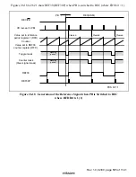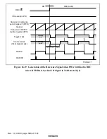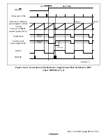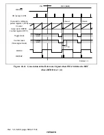
Rev. 1.0, 02/00, page 591 of 1141
26.4.3
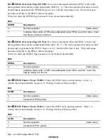
HSW Timing Generator Configuration
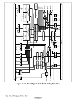
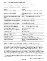
The HSW timing generator is composed of the elements shown in table 26.5.
Table 26.5
Configuration of the HSW Timing Generator
Element
Function
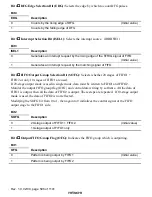
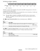
HSW mode register 1 (HSM1)
Confirmation/determination of this circuits' operating
status
HSW mode register 2 (HSM2)
Confirmation/determination of this circuits' operating
status
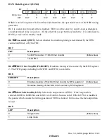
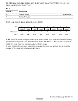
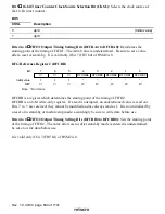
HSW loop stage number setting register
(HSLP)
Setting of number of loop stages in loop mode
FIFO output pattern register 1 (FPDRA)
Output pattern register of FIFO1
FIFO output pattern register 2 (FPDRB)
Output pattern register of FIFO2
FIFO timing pattern register 1 (FTPRA)
Output timing register of FIFO1
FIFO timing pattern register 2 (FTPRB)
Output timing register of FIFO2
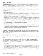
DFG reference register 1 (DFCRA)
Setting of reference DFG edge for FIFO1
DFG reference register 2 (DFCRB)
Setting of reference DFG edge for FIFO2
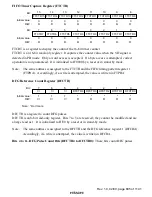
FIFO timer capture register (FTCTR)
Capture register of timer counter
DFG reference count register (DFCTR)
DFG edge count
FIFO control circuit
FIFO status control
DFG count compare circuit (
×
2)
Detection of match between DFCR and DFG counters
16-bit timer counter
16-bit free-run timer counter
31-bit x 20 stage FIFO
First In First Out data buffer
31-bit FIFO data buffer
Data storing buffer for the first stage of FIFO
16-bit compare circuit
Detection of match between timer counter and FIFO
data buffer
FPDRA and FPDRB are intermediate buffers; an FTPRA and FTPRB write results in
simultaneous writing of all 31 bits to the FIFO. The FIFO has two 31-bit x 10-stage data buffers;
its operating status is controlled by HSM1 and HSM2. Data is stored in the 31-bit data buffer.
The values of FTPRA/FTPRB and the timer counter are compared, and if they match, the 15-bit
pattern data is output to each function. AudioFF, VideoFF, and PPG (P70 to P77) are outputs
from the corresponding pins, ADTRG is the A/D converter hardware start signal, Vpulse and
Mlevel signals are the signals for generating the additional V pulses, and HSW and NHSW signals
are the same as VideoFF signals used for the phase control of the drum. The 16-bit timer counter
is initialized by the overflow of the 19-bit free-run counter in the free-run mode (FRT bit of HSM2
= 1), or by a signal indicating a match between DFCRA/DFCRB and the 5-bit DFG counter in
DFG reference mode.

